SmartSwitch Router User Reference Manual
9032578-02
SSR User Reference Manual
FCC Notice
Vcci Notice
Declaration of Conformity Addendum
SSR User Reference Manual
Contents
IP Routing Configuration Guide
RIP Configuration Guide
Assigning IP/IPX Interfaces
Routing Policy Configuration Guide 107
143
Creating IPX Interfaces 153
Security Configuration Guide 161
185
Contents
Who Should Read This Manual?
Preface
About This Manual
How to Use This Manual
Related Documentation
If You Want To See
For Information About See
Chapter SmartSwitch Router Product Overview
SSR Hardware and software specifications
Feature Specification
Supported Media Encapsulation Type
Supported Routing Protocols
Configuring the Cabletron SmartSwitch Router
Understanding the Command Line Interface
Basic Line Editing Commands
Common CLI key commands
Access Modes
User Mode
Enable Mode
Ospf
Configure Mode
Disabling a Function or Feature
Loading System Images and Configuration Files
Boot Prom Mode
Loading System Image Software
Boot and System Image
Configuration Files
Loading Boot Prom Software
Enter the system image list command to verify the change
Activate the Configuration Commands in the Scratchpad
Ctron-ssr-1#system show version
Copy the Configuration to the Startup Configuration File
Managing the SSR
CLI displays the following message
Enter yes or y to activate the changes
Configure NTP
Configure the SSR CLI
Set SSR Name
Set SSR Date and Time
Configure DNS
Monitoring Configuration
Configure Snmp Services
Task Command
Spanning Tree Ieee 802.1d
Chapter Bridging Configuration Guide
Bridging Overview
Vlan Overview
Bridging Modes Flow-Based and Address-Based
Port-based VLANs
MAC-address-based VLANs
Protocol-based VLANs
Subnet-based VLANs
SSR Vlan Support
Multicast-based VLANs
Policy-based VLANs
VLANs and the SSR
Access Ports and Trunk Ports 802.1Q support
Ports, VLANs, and L3 Interfaces
Explicit and Implicit VLANs
Configuring SSR Bridging Functions
Configure Address-based or Flow-based Bridging
Configuring Spanning Tree
Address-Based Bridge Table Flow-Based Bridge Table
Adjust Spanning-Tree Parameters
Enable spanning tree on one or more ports
Set the Bridge Priority
Set a Port Priority
Adjust Bridge Protocol Data Unit Bpdu Intervals
Adjust the Interval between Hello Times
Define the Forward Delay Interval
Assign Port Costs
Configuring a Port or Protocol based Vlan
Configuring Vlan Trunk Ports
Define the Maximum Age
Create a Port or Protocol Based Vlan
Monitor Bridging
Configure Bridging for Non-IP/IPX Protocols
Configure Layer-2 Filters
Configuration Examples
Creating an IP or IPX Vlan
Chapter IP Routing Configuration Guide
IP Routing Overview
IP Routing Protocols
SSR supports standards based TCP, UDP, and IP
Unicast Routing Protocols
Multicast Routing Protocols
Configuring IP Interfaces and Parameters
Configure IP Addresses to Ports
Configure IP Interfaces for a Vlan
Specify Ethernet Encapsulation Method
Configure Proxy ARP
Configure Address Resolution Protocol
Configure ARP Cache Entries
Configure DNS Parameters
Configure IP Services Icmp
Configure IP Helper
Specify ping
Configure Direct Broadcast
Monitor IP Parameters
Show DNS parameters
Assigning IP/IPX Interfaces
Show ARP entries in routing table
Page
RIP Overview
Chapter RIP Configuration Guide
Configure RIP
Enabling and Disabling RIP
Configuring RIP Interfaces
Configure RIP Parameters
Configure RIP Route Preference
Configure RIP Route Default-Metric
Monitoring RIP
Show detailed information of response
Configuration Example
Packets sent by the router Show RIP timer information
Page
Ospf Overview
Configuration Guide
Chapter
Configure Ospf
Enable Ospf
Enable Ospf
Disable Ospf
Ospf Interface Parameters
Configure Ospf Interface Parameters
Ospf Parameter Default Value
Add an interface to an Ospf area
Configure an Ospf Area
Create an Ospf area
Configure Ospf Area Parameters
Create Virtual Links
Add a stub host to an Ospf area
Add a network to an Ospf area for
Configure Ospf over Non-Broadcast Multiple Access
Create a virtual
Link
Set virtual link
Monitoring Ospf
Ospf Configuration Examples
Exporting All Interface & Static Routes to Ospf
Export All RIP, Interface & Static Routes to Ospf
Create a Ospf export destination for type-1 routes
Create a Ospf export destination for type-2 routes
Create a RIP export source
Create a Static export source
Create OSPF-ASE export source
Create a RIP export destination
Create Ospf export source
R10
Chapter BGP Configuration Guide
BGP Overview
Basic BGP Tasks
SSR BGP Implementation
Setting the Autonomous System Number
Setting the Router ID
Configuring a BGP Peer Group
Ip-router global set autonomous-system num1 loops num2
Where
Autonomous-system number
Using AS-Path Regular Expressions
Adding a BGP Peer
Starting BGP
Bgp add network ip-addr-maskall group number
AS-Path Regular Expression Examples
To import MCI routes with a preference
Using the AS Path Prepend Feature
BGP Configuration Examples
BGP Peering Session Example
AS-1 AS-2
Physical Link Peering Relationship
Gated.conf file for router SSR1 is as follows
CLI configuration for router SSR1 is as follows
CLI configuration for router SSR2 is as follows
Ibgp Routing Group Example
Ibgp Configuration Example
Gated.conf file for router SSR2 is as follows
Sample Ibgp Configuration Routing Group Type
AS-64801
Following lines in the Cisco router configure Ospf
Ibgp Internal Group Example
Illustrates a sample Ibgp Internal group configuration
Sample Ibgp Configuration Internal Group Type
Gated.conf file for router SSR1 is as follows
Configuration for router C2 a Cisco router is as follows
Ebgp Multihop Configuration Example
Configuration for router C1 a Cisco router is as follows
AS-64800
Physical Link
CLI configuration for router SSR3 is as follows
CLI configuration for router SSR4 is as follows
Community Attribute Example
Gated.conf file for router SSR3 is as follows
Gated.conf file for router SSR4 is as follows
Sample BGP Configuration Specific Community
Sample BGP Configuration Well-Known Community
, router SSR11 has the following configuration
, router SSR13 has the following configuration
, router SSR10 has the following configuration
, router SSR14 has the following configuration
BGP Configuration Guide
LocalPref Attribute Example
Sample BGP Configuration LocalPref Attribute
Multi-Exit Discriminator Attribute Example
Sample BGP Configuration MED Attribute
Router SSR6 has the following CLI configuration
Router SSR8 has the following CLI configuration
Ebgp Aggregation Example
AS-64900
AS-64901
Router SSR9 has the following CLI configuration
Route Reflection Example
Shows a sample configuration that uses route reflection
AS-64902
Bgp set peer-group rtr11 reflector-client
SmartSwitch Router User Reference Manual 105
106
Chapter Routing Policy Configuration Guide
Route Import and Export Policy Overview
Preference
Default Preference Values
Preference Defined by CLI Command Default
Import Policies
Import-Source
Export Policies
Route-Filter
Export-Destination
Export-Source
Specifying a Route Filter
Aggregates and Generates
Aggregate-Destination
Aggregate-Source
Authentication
Authentication Methods
Configure Simple Routing Policies
Authentication Keys and Key Management
Redistributing Static Routes
Redistributing Directly Attached Networks
Redistributing RIP into RIP
Redistributing RIP into Ospf
Redistributing Ospf to RIP
Redistributing Aggregate Routes
Simple Route Redistribution Examples
To redistribute aggregate
Routes into Ospf
Example 1 Redistribution into RIP
Example 2 Redistribution into Ospf
Exporting a Given Static Route to All RIP Interfaces
Exporting All Static Routes to All RIP Interfaces
120
Configure Advanced Routing Policies
122
Creating an Export Destination
Creating an Export Source
Creating an Import Source
Creating a Route Filter
Creating an Aggregate Route
Create a RIP import
SmartSwitch Router User Reference Manual 125
Creating an Aggregate Destination
Creating an Aggregate Source
Examples of Import Policies
Example 1 Importing from RIP
R41
128
Example 2 Importing from Ospf
130
131 Routing Policy Configuration
Importing a Selected Subset of OSPF-ASE Routes
Examples of Export Policies
Example 1 Exporting to RIP
Ip-router policy create rip-export-source ripExpSrc
Exporting a Given Static Route to a Specific RIP Interface
Exporting Aggregate-Routes into RIP
Ip-router policy create aggr-export-source aggrExpSrc
Example 2 Exporting to Ospf
SmartSwitch Router User Reference Manual 139
Exporting All RIP, Interface & Static Routes to Ospf
SmartSwitch Router User Reference Manual 141
142
Igmp Overview
Chapter Multicast Routing Configuration Guide
IP Multicast Overview
Dvmrp Overview
Configure Igmp
Configuring Igmp on an IP Interface
Configure Igmp Query Interval
Configure Igmp Response Wait Time
Starting and Stopping Dvmrp
Configure Dvmrp
Configure Per-Interface Control of Igmp Membership
Configure the Dvmrp Routing Metric
Configure Dvmrp on an Interface
Configure Dvmrp Parameters
Configure Dvmrp TTL & Scope
Configure a Dvmrp Tunnel
Monitor Igmp & Dvmrp
Show all multicast routes
Show all interfaces running
Multicast protocols Igmp
RIP Routing Information Protocol
Chapter IPX Routing Configuration Guide
IPX Routing Overview
SAP Service Advertising Protocol
IPX Addresses
Configuring IPX RIP & SAP
Creating IPX Interfaces
Configuring IPX Interfaces and Parameters
Configure IPX Addresses to Ports
Configure IPX Interfaces for a Vlan
Specify IPX Encapsulation Method
Configure IPX Routing
Enable IPX RIP
Enable SAP
Configure Static Routes
Create an IPX Access Control List
Configure Static SAP Table Entries
Control Access to IPX Networks
Create an IPX GNS Access Control List
Create an IPX Type 20 Access Control List
Create an IPX SAP Access Control List
Create an IPX RIP Access Control List
Monitor an IPX Network
Adds a SAP access list Adds a GNS access list
160
Chapter Security Configuration Guide
Security Overview
Configuring SSR Access Security
Configure Radius
Configure Tacacs
Monitor Radius
Monitor Tacacs Plus
Configure Tacacs Plus
Monitor Tacacs
Configure Passwords
Layer-2 Security Filters
Configuring Layer-2 Address Filters
Configuring Layer-2 Port-to-Address Lock Filters
Configuring Layer-2 Static Entry Filters
Configuring Layer-2 Secure Port Filters
Configure a source static
Configure a destination static
Monitor Layer-2 Security Filters
Layer-2 Filter Examples
Et.1.1 et.1.2et.1.3
Hub
Engineers, Consultant Engineering Finance File Servers
Port-to-Address Lock Examples
Example 2 Secure Ports
Anatomy of an ACL Rule
Layer-3 Access Control Lists ACLs
Layer-3 & Layer-4 Traffic Filters Access Control List
Ordering of ACL Rules
Implicit Deny Rule
Applying ACLs to Interfaces
Applying ACLs to Services
ACL Logging
Maintaining ACLs Offline Using Tftp or RCP
Defining an IP ACL
Maintaining ACLs Using the ACL Editor
Configure ACL
Monitoring Access Control Lists
Applying an ACL to a Service
Defining an IPX ACL
Applying an ACL to an Interface
Show ACLs on all IPX interfaces
QoS & Layer-2/Layer-3/Layer-4 Flow Overview
Chapter QoS Configuration Guide
Layer-2, Layer-3 & Layer-4 Flow Specification
Precedence for Layer-3 Flows
SSR Queuing Policies
Configure Layer-2 QoS
Configuring Layer-3 & Layer-4 QoS
Configuring IP QoS Policies
Configuring IPX QoS Policies
Setting an IP QoS Policy
Specifying Precedence for an IP QoS Policy
Configuring SSR Queueing Policy
Allocating Bandwidth for a Weighted-Fair Queuing Policy
Setting an IPX QoS Policy
Specifying Precedence for an IPX QoS Policy
Monitoring QoS
Show all IP QoS flows
Show all IPX QoS flows
Show all Layer-2 QoS flows
Chapter Performance Monitoring Guide
Performance Monitoring Overview
Bridging mode Show information about the master
Show port error statistics
Show all L2 flows for ports in flow
MAC table Show information about a
Configuring the SSR for Port Mirroring
Port port list
188
Hot Swapping Line Cards
Chapter Hot Swapping Line Cards Control Modules
Hot Swapping Overview
Deactivating the Line Card
Removing the Line Card
To deactivate the line card, do one of the following
To remove a line card from the SSR
Installing a New Line Card
To install a new line card
Hot Swapping a Secondary Control Module
Hot Swapping One Type of Line Card With Another
Deactivating the Control Module
Removing the Control Module
To deactivate the Control Module
To remove a Control Module from the SSR
Hot Swapping a Switching Fabric Module SSR 8600 only
Installing the Control Module
To install a new Control Module or line card into the slot
To deactivate the Switching Fabric Module
To remove the Switching Fabric Module
To install a Switching Fabric Module
Configuring Vrrp
Vrrp Overview
Basic Vrrp Configuration
Backup
Configuration of Router R1
Following is the configuration file for Router R1 in Figure
Following is the configuration file for Router R2 in Figure
Symmetrical Configuration
Configuration for Router R2
Master for VRID=1 Master for VRID=2 Backup for VRID=2
Symmetrical Vrrp Configuration
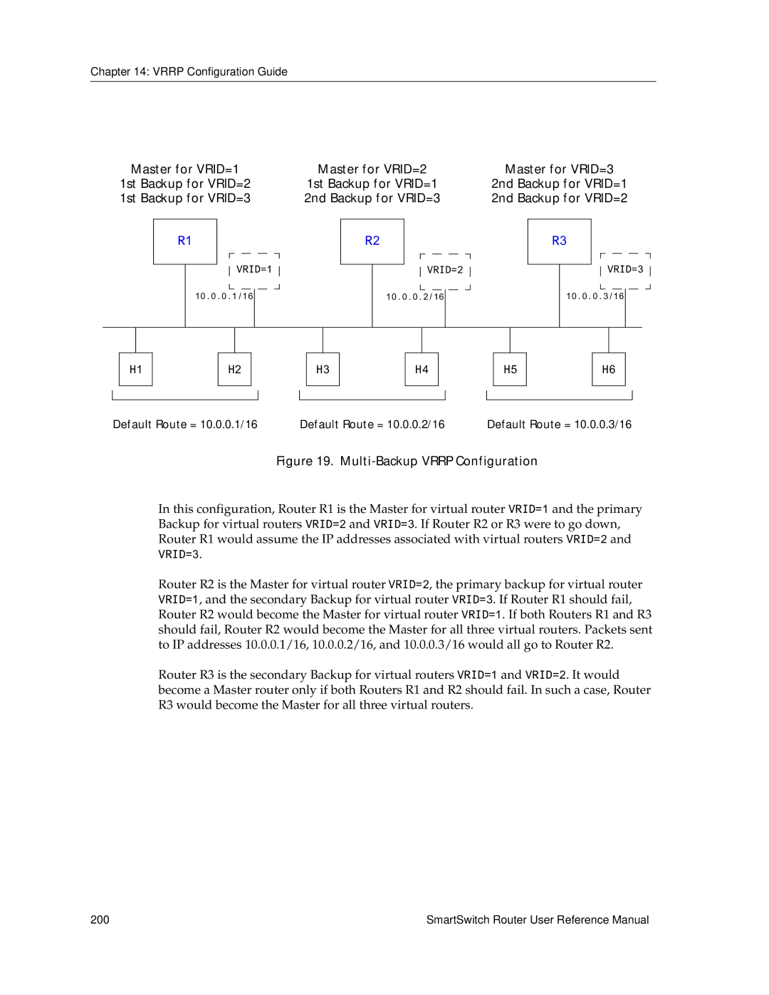
Multi-Backup Configuration
Configuration of Router R2
Multi-Backup Vrrp Configuration
SmartSwitch Router User Reference Manual 201
Virtual Router Default Priority Configured Priority
Following is the configuration file for Router R3 in Figure
Additional Configuration
Configuration of Router R3
Setting Pre-empt Mode
Setting the Backup Priority
Setting the Advertisement Interval
Ip-redundancy trace
Setting an Authentication Key
Monitoring Vrrp
Vrrp Configuration Notes
Ip-redundancy show
Virtual routers Display information about all
Specific virtual router
SmartSwitch Router User Reference Manual 207