Earthing
Finally, some consideration should be given to the earthing arrangement of the system, at the centre of which is the console and the MPS14. The console chassis is earthed, to the mains earth, via the power supply. When
Using the MPS14
The MPS14 will operate from an ac mains supply voltage from 100V to 240V. Before switching on the power supply, check that the ac mains fuse is of the correct type and rating. This is marked on the rear panel of the power unit. The power supply is provided with an IEC type mains connector and a moulded mains plug. Check that this is suitable for connection to the wall socket outlet.
Always switch the power supply off before connecting or disconnecting the console power cables, removing or installing console modules and any servicing work. In the event of an electrical storm, or large mains voltage fluctuations, immediately switch off the power supply and disconnect from the mains supply.
During normal operation some heat is generated. This is expelled via the front panel ventilation holes.
Combining MPS14 Power units
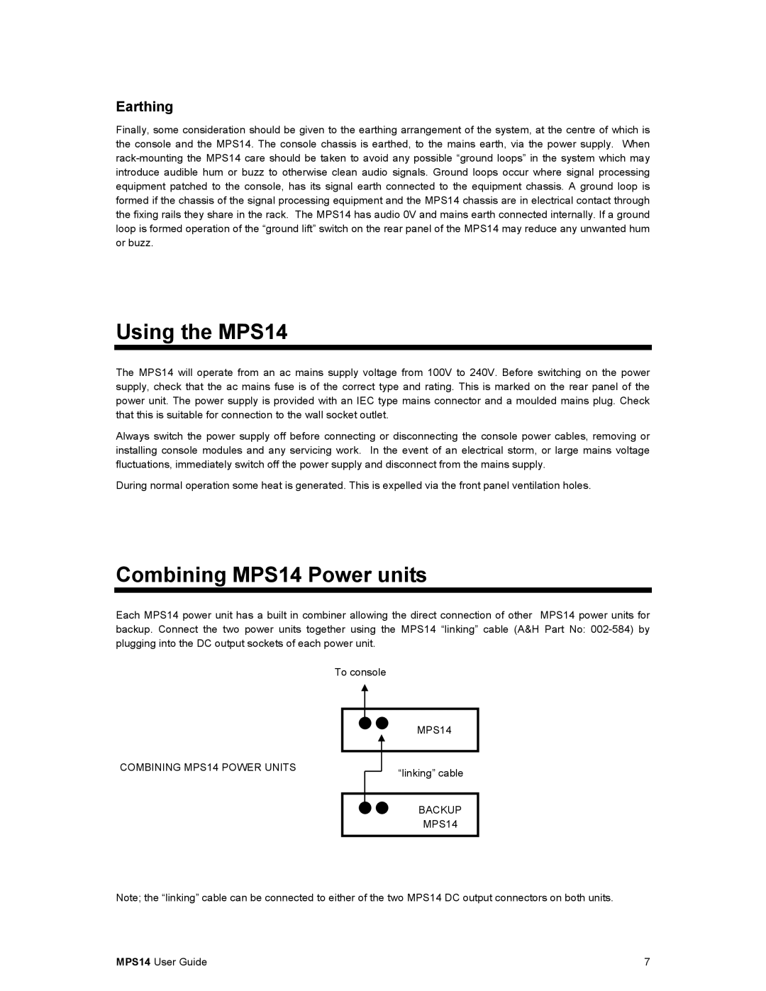
Each MPS14 power unit has a built in combiner allowing the direct connection of other MPS14 power units for backup. Connect the two power units together using the MPS14 “linking” cable (A&H Part No:
To console
COMBINING MPS14 POWER UNITS
MPS14 |
“linking” cable
BACKUP
MPS14
Note; the “linking” cable can be connected to either of the two MPS14 DC output connectors on both units.
MPS14 User Guide | 7 |
