SSIM-T5-04 Token Ring
SmartStack Interface Module
Introduction
The SmartStack
DIAG
ERR
1 | 2 | 3 | 4 |
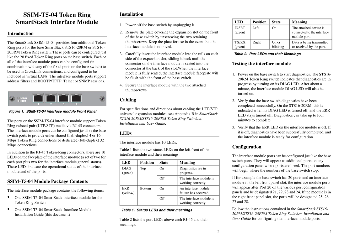
Figure 1. SSIM-T5-04 interface module Front Panel
The ports on the
In addition to the
These LEDs indicate the operational status of the interface module and of the ports.
SSIM-T5-04 Module Package Contents
The interface module package contains the following items:
•One
•One
Installation
1.Power off the base switch by unplugging it.
2.Remove the plate covering the expansion slot on the front of the base switch by unscrewing the two retaining thumbscrews. Keep the plate for use in the event that the interface module is removed.
3.Carefully insert the interface module into the rails on each side of the expansion slot, sliding it back until the connector on the interface module is seated into the connector at the back of the slot.When the interface module is fully seated, the interface module faceplate will be flush with the front of the base switch.
4.Secure the interface module with the two attached thumbscrews.
Cabling
For specifications and directions about cabling the UTP/STP universal expansion modules, see Appendix B in SmartStack
LEDs
The interface module has 10 LEDs.
Table 1 lists the two status LEDs on the left front of the interface module and their meanings.
LED | Position | State | Meaning |
|
|
|
|
|
|
|
|
DIAG | Top | On | Diagnostics are in |
(green) |
|
| progress. |
|
|
|
|
|
| Off | The interface module is |
|
|
| working correctly. |
|
|
|
|
ERR | Bottom | On | An interface module |
(yellow) |
|
| failure has occurred. |
|
|
|
|
|
| Off | The interface module is |
|
|
| working correctly. |
|
|
|
|
Table 1. Status LEDs and their meanings
Table 2 lists the port LEDs above each
LED | Position | State | Meaning |
|
|
|
|
INSRT | Left | On | The attached device is |
(green) |
|
| connected to the interface |
|
|
| module port. |
|
|
|
|
TX/RX | Right | On or | Data is being transmitted |
(green) |
| blinking | or received by the port. |
|
|
|
|
Table 2. Port LEDs and their Meanings
Testing the interface module
1.Power on the base switch to start diagnostics. The STS16- 20RM Token Ring switch indicates that diagnostics are in progress by turning on its DIAG LED. After about a minute, the interface module DIAG LED will also be turned on.
2.Verify that the base switch diagnostics have been completed successfully. On the
3.Verify that the ERR LED on the interface module is off. If it is off, diagnostics have been successfully completed, and the interface module is ready for configuration.
Configuration
The interface module ports can be configured just like the base switch ports. They will appear as additional ports on any configuration panel where ports are listed. The port numbers will begin where the numbers of the base switch stop.
If for example the base switch has 20 ports and an interface module in the left front panel slot, the interface module ports will appear after Port 20 on the various port configuration panels and be designated 21, 22, 23 and 24. If the module is in the right front panel slot, the ports will be designated 25, 26, 27 and 28.
Follow the instructions contained in the SmartStack STS16-
1 | 2 | 3 |