Chapter 2: Installation
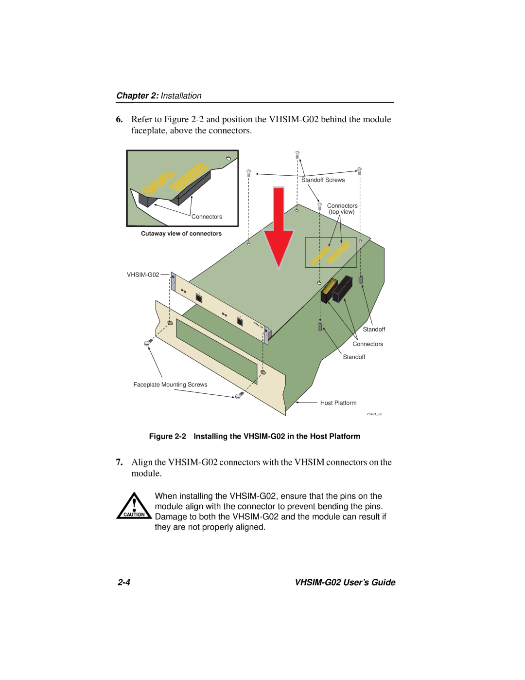
6.Refer to Figure
Connectors |
Cutaway view of connectors
VHSIM-G02
1
2
VHSIM-
G02
SP
Standoff Screws
Connectors (top view)
Standoff
Connectors
Standoff
Faceplate Mounting Screws
Host Platform
25491_36
Figure 2-2 Installing the VHSIM-G02 in the Host Platform
7.Align the
When installing the
!module align with the connector to prevent bending the pins.
CAUTION | Damage to both the |
| |
| they are not properly aligned. |
|