Operation ( C o n t i n u e d )
3 . The safety valve should automatically close at approximately
Safety valve must be replaced if it
cannot be actuated or it leaks air after ring is released.
PRESSURE GAUGES
Gauge attached to regulator indicates air pressure going to hose (and any tool attached to end of hose).
Gauge attached to pressure switch indicates air pressure in tank.
M a i n t e n a n c e
Disconnect power source and then release all pressure from the system before attempting to install, service, relocate or perform any
m a i n t e n a n c e .
Check compressor often for any visible problems and follow maintenance procedures each time compressor is u s e d .
1 . Turn compressor off and release pressure from system. To release pressure from system, pull ring on ASME safety valve (see Figures 6 and 8 ). Deflect escaping air by shielding valve with one hand as you pull ring with other hand. Pull ring until tank is empty.
A large amount of fast moving air will
be released when the safety valve is opened with pressure in the tank. Wear ANSI approved Z87.1 safety glasses.
2 . Drain moisture from tank by opening drain valve (see Figure 6) underneath tank. Tilt tank to remove all
m o i s t u r e .
3 . Clean dust and dirt from tank, air lines and pump cover while compressor is still OFF.
OIL CHANGE
1 . Allow compressor to run and warm up oil. Unplug unit.
2 . Position a pan under pump end of u n i t .
3 . Remove oil drain plug (see Figure 6). Allow oil to collect in pan. Tilt unit to completely drain.
4 . Replace drain plug, fill pump to full line on sight glass. Use Chevron synthetic
5 . Change oil after every 50 hours of u s e .
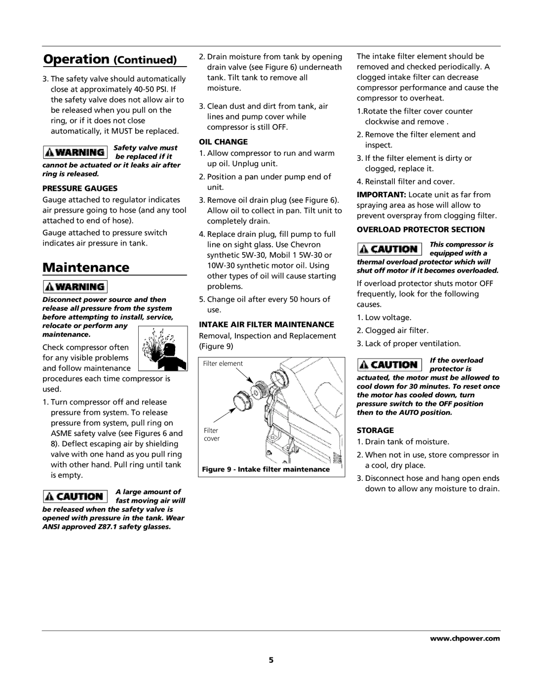
I N T A K E AIR FILTER MAINTENANCE
Removal, Inspection and Replacement (Figure 9)
Filter element
F i l t e r c o v e r
Figure 9 - Intake filter maintenance
The intake filter element should be removed and checked periodically. A clogged intake filter can decrease compressor performance and cause the compressor to overheat.
1.Rotate the filter cover counter clockwise and remove .
2 . Remove the filter element and i n s p e c t .
3 . If the filter element is dirty or clogged, replace it.
4 . Reinstall filter and cover.
IMPORTANT: Locate unit as far from spraying area as hose will allow to prevent overspray from clogging filter.
OVERLOAD PROTECTOR SECTION
This compressor is equipped with a
thermal overload protector which will shut off motor if it becomes overloaded.
If overload protector shuts motor OFF frequently, look for the following
c a u s e s .
1 . Low voltage.
2 . Clogged air filter.
3 . Lack of proper ventilation.
If the overload protector is
actuated, the motor must be allowed to cool down for 30 minutes. To reset once the motor has cooled down, turn pressure switch to the OFF position then to the AUTO position.
S T O R A G E
1 . Drain tank of moisture.
2 . When not in use, store compressor in a cool, dry place.
3 . Disconnect hose and hang open ends down to allow any moisture to drain.
w w w . c h p o w e r . c o m
5
