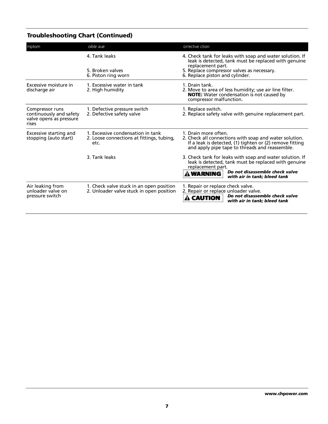
Troubleshooting Chart (Continued)
| Symptom | Possible Cause(s) | Corrective Action |
| ||
|
|
|
|
|
| |
|
| 4 . Tank leaks | 4 | . Check tank for leaks with soap and water solution. If |
| |
|
|
|
|
| leak is detected, tank must be replaced with genuine |
|
|
|
|
|
| replacement part. |
|
|
| 5. | Broken valves | 5 | . Replace compressor valves as necessary. |
|
|
| 6. | Piston ring worn | 6 | . Replace piston and cylinder. |
|
|
|
|
|
|
| |
| Excessive moisture in | 1 . Excessive water in tank | 1 | . Drain tank. |
| |
| discharge air | 2 . High humidity | 2 | . Move to area of less humidity; use air line filter. |
| |
|
|
|
|
| NOTE: Water condensation is not caused by |
|
|
|
|
|
| compressor malfunction. |
|
|
|
|
|
|
| |
| Compressor runs | 1 . Defective pressure switch | 1 | . Replace switch. |
| |
| continuously and safety | 2 . Defective safety valve | 2 | . Replace safety valve with genuine replacement part. |
| |
| valve opens as pressure |
|
|
|
|
|
| r i s e s |
|
|
|
|
|
|
|
|
|
|
| |
| Excessive starting and | 1. Excessive condensation in tank | 1 | . Drain more often. |
| |
| stopping (auto start) | 2 . Loose connections at fittings, tubing, | 2 | . Check all connections with soap and water solution. |
| |
|
|
| e t c . |
| If a leak is detected, (1) tighten or (2) remove fitting |
|
|
|
|
|
| and apply pipe tape to threads and reassemble. |
|
|
| 3 . Tank leaks | 3 | . Check tank for leaks with soap and water solution. If |
| |
|
|
|
|
| leak is detected, tank must be replaced with genuine |
|
|
|
|
|
| replacement part. |
|
|
|
|
|
| Do not disassemble check valve |
|
|
|
|
|
| with air in tank; bleed tank |
|
|
|
|
|
|
| |
| Air leaking from | 1 . Check valve stuck in an open position | 1 | . Repair or replace check valve. |
| |
| unloader valve on | 2 . Unloader valve stuck in open position | 2 | . Repair or replace unloader valve. |
| |
| pressure switch |
|
|
| Do not disassemble check valve |
|
|
|
|
|
| with air in tank; bleed tank |
|
|
|
|
|
|
|
|
w w w . c h p o w e r . c o m
7
