Diagnostics
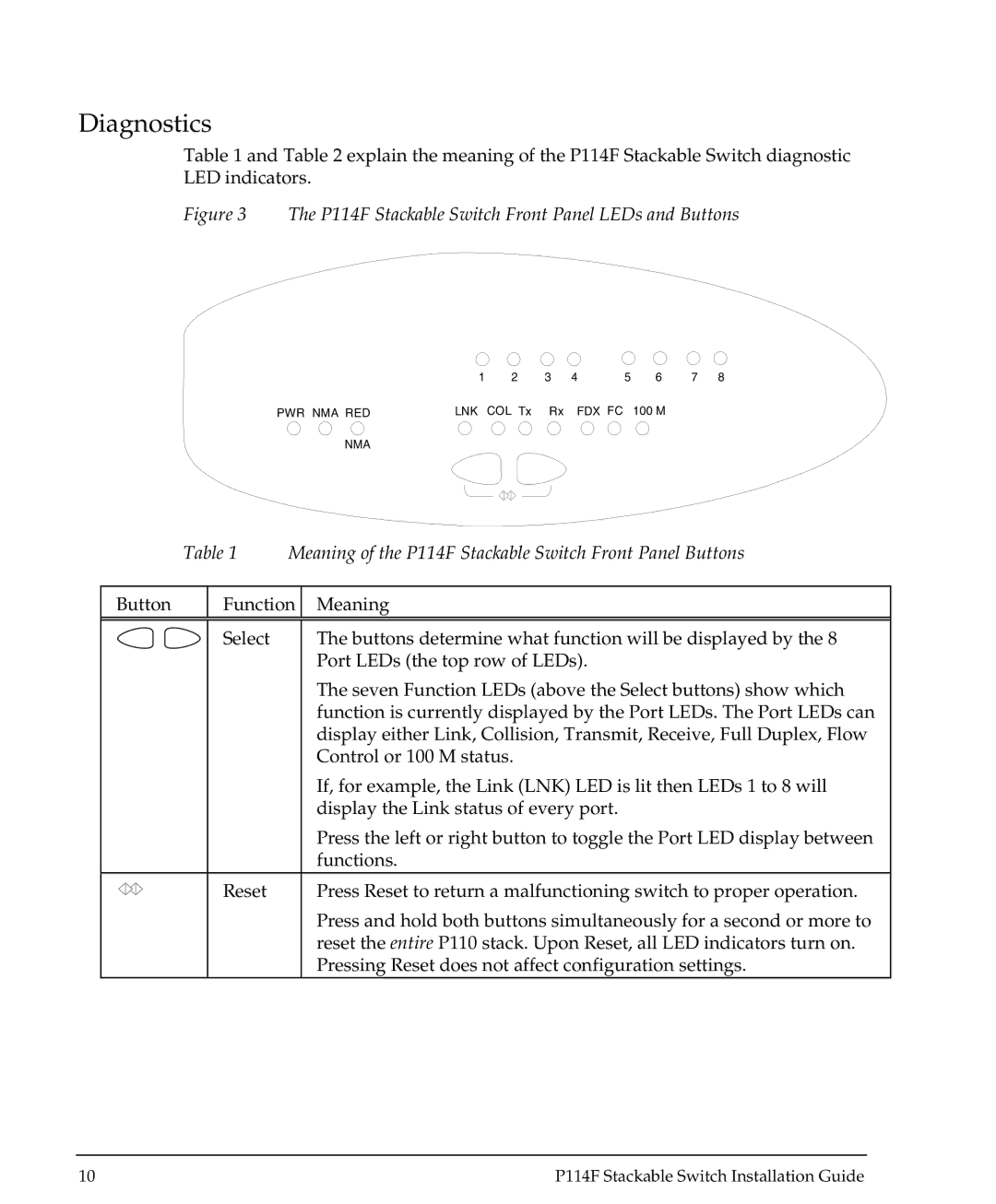
Table 1 and Table 2 explain the meaning of the P114F Stackable Switch diagnostic LED indicators.
Figure 3 The P114F Stackable Switch Front Panel LEDs and Buttons
| 1 | 2 | 3 | 4 | 5 | 6 | 7 | 8 |
PWR NMA RED | LNK | COL Tx | Rx | FDX FC |
| 100 M |
|
|
NMA |
|
|
|
|
|
|
|
|
Table 1 Meaning of the P114F Stackable Switch Front Panel Buttons
Button | Function | Meaning | ||
|
|
|
|
|
|
|
| Select | The buttons determine what function will be displayed by the 8 |
|
|
|
| Port LEDs (the top row of LEDs). |
|
|
|
| The seven Function LEDs (above the Select buttons) show which |
|
|
|
| function is currently displayed by the Port LEDs. The Port LEDs can |
|
|
|
| display either Link, Collision, Transmit, Receive, Full Duplex, Flow |
|
|
|
| Control or 100 M status. |
|
|
|
| If, for example, the Link (LNK) LED is lit then LEDs 1 to 8 will |
|
|
|
| display the Link status of every port. |
|
|
|
| Press the left or right button to toggle the Port LED display between |
|
|
|
| functions. |
|
|
| Reset | Press Reset to return a malfunctioning switch to proper operation. |
|
|
| ||
|
|
| ||
|
|
|
| Press and hold both buttons simultaneously for a second or more to |
|
|
|
| reset the entire P110 stack. Upon Reset, all LED indicators turn on. |
|
|
|
| Pressing Reset does not affect configuration settings. |
10 | P114F Stackable Switch Installation Guide |