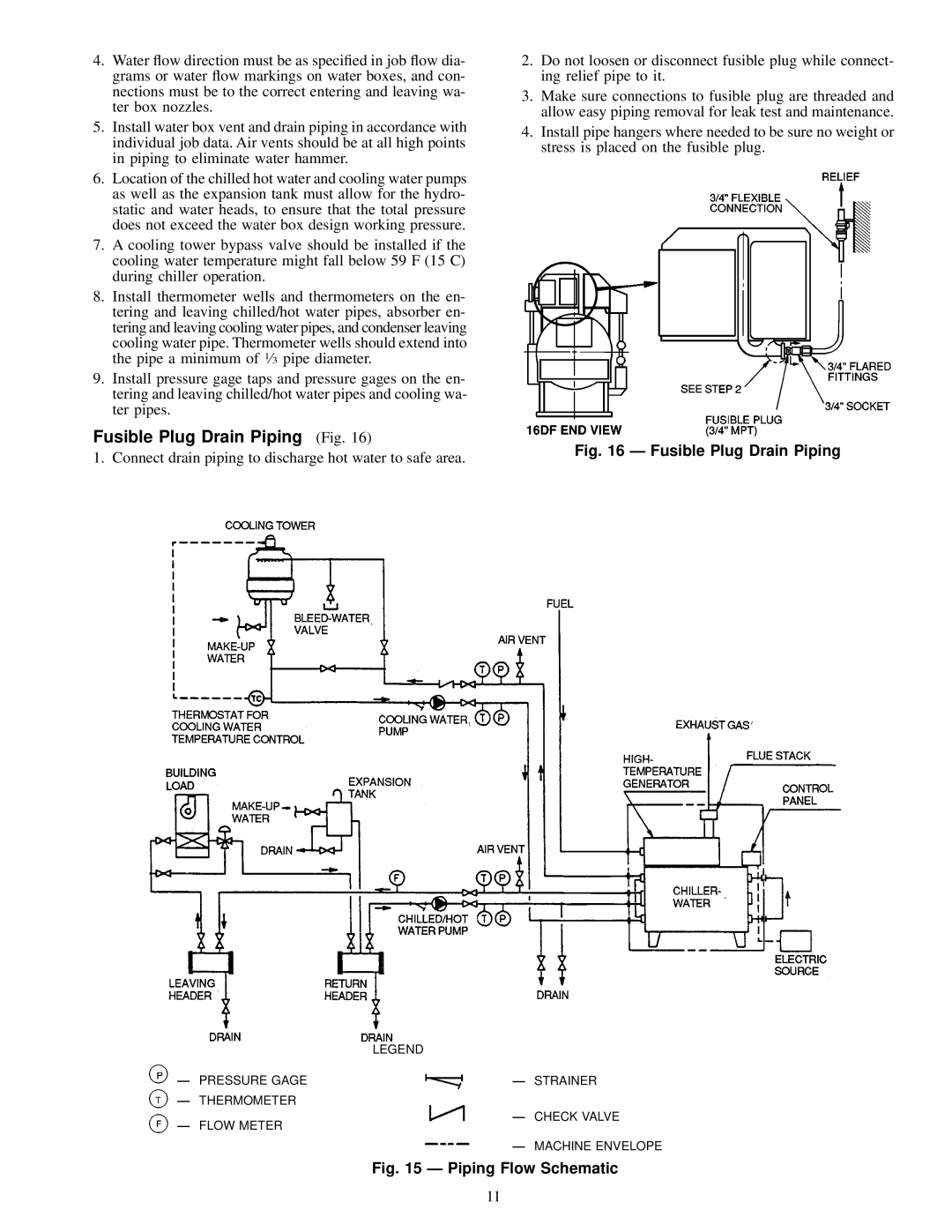
16DF013-050 specifications
The Carrier 16DF013-050 is an advanced air conditioning unit designed for superior performance and efficiency in residential and light commercial applications. Renowned for its reliable cooling capabilities, this model incorporates state-of-the-art technologies and features that enhance user comfort while minimizing energy consumption.One of the standout characteristics of the Carrier 16DF013-050 is its high SEER (Seasonal Energy Efficiency Ratio) rating, which guarantees efficient cooling during the peak summer months. This unit is designed to operate at optimal efficiency, thereby reducing energy bills and providing substantial savings over time. Its innovative design minimizes energy use while delivering consistent comfort throughout the space.
The Carrier 16DF013-050 utilizes advanced scroll compressor technology, which ensures quiet operation and reduces vibrations, enhancing overall durability. This technology allows the unit to effectively modulate its cooling output according to demand, ensuring that the environment remains comfortable without wasting energy. Additionally, the unit is equipped with advanced diagnostics that make it easier for technicians to identify any maintenance issues promptly, reducing downtime and repair costs.
Another notable feature of this model is the inclusion of Carrier’s proprietary Infinity® control system, which provides users with the ability to manage their indoor climate through a user-friendly interface. The system enables remote control capabilities via smartphone apps, allowing for seamless integration into smart home systems. This means users can monitor and adjust their air conditioning settings even when they are not at home, ensuring optimal comfort at all times.
Durability is another hallmark of the Carrier 16DF013-050. The unit is built with high-quality materials that withstand harsh weather conditions, ensuring longevity and reliable operation. The cabinet is galvanized and powder-coated, providing an added layer of protection against rust and corrosion.
The Carrier 16DF013-050 is also designed with eco-conscious considerations in mind, utilizing R-410A refrigerant, which is less harmful to the environment compared to older refrigerants. This aligns with Carrier’s commitment to sustainability and energy efficiency.
In summary, the Carrier 16DF013-050 is an exemplary model in the realm of air conditioning systems. With its high efficiency, state-of-the-art compressor technology, advanced control options, and eco-friendly features, it offers an excellent solution for maintaining comfortable indoor climates while being mindful of energy consumption and environmental impact.

