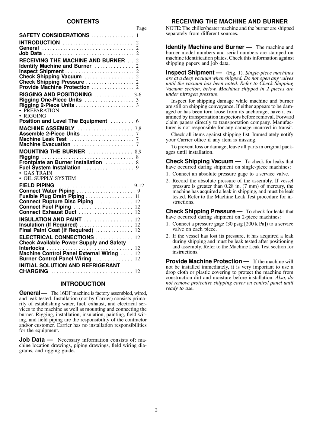
CONTENTS

Page

SAFETY CONSIDERATIONS . . . . . . . . . . . . . . . . 1

INTRODUCTION . . . . . . . . . . . . . . . . . . . . . . . . . . 2

General . . . . . . . . . . . . . . . . . . . . . . . . . . . . . . . . . . 2

Job Data . . . . . . . . . . . . . . . . . . . . . . . . . . . . . . . . . . 2

RECEIVING THE MACHINE AND BURNER . . 2

Identify Machine and Burner . . . . . . . . . . . . . . 2

Inspect Shipment . . . . . . . . . . . . . . . . . . . . . . . . . . 2

Check Shipping Vacuum . . . . . . . . . . . . . . . . . . 2

Check Shipping Pressure . . . . . . . . . . . . . . . . . . 2

Provide Machine Protection . . . . . . . . . . . . . . . . 2

RIGGING AND POSITIONING . . . . . . . . . . . . . . 3-6

Rigging One-Piece Units . . . . . . . . . . . . . . . . . . 3

Rigging 2-Piece Units . . . . . . . . . . . . . . . . . . . . . . 3

·PREPARATION

·RIGGING

Position and Level The Equipment . . . . . . . . 6

MACHINE ASSEMBLY . . . . . . . . . . . . . . . . . . . . 7,8

Assemble 2-Piece Units . . . . . . . . . . . . . . . . . . . . 7

Machine Leak Test . . . . . . . . . . . . . . . . . . . . . . . . 7

Machine Evacuation . . . . . . . . . . . . . . . . . . . . . . 7

MOUNTING THE BURNER . . . . . . . . . . . . . . . . 8,9

Rigging . . . . . . . . . . . . . . . . . . . . . . . . . . . . . . . . . . 8

Frontplate an Burner Installation . . . . . . . . . . 8

Fuel System Installation . . . . . . . . . . . . . . . . . . 9

·GAS TRAIN

·OIL SUPPLY SYSTEM

FIELD PIPING . . . . . . . . . . . . . . . . . . . . . . . . . . . . 9-12

Connect Water Piping . . . . . . . . . . . . . . . . . . . . . . 9

Fusible Plug Drain Piping . . . . . . . . . . . . . . . . . . 11

Connect Rupture Disc Piping . . . . . . . . . . . . . . 12

Connect Fuel Piping . . . . . . . . . . . . . . . . . . . . . . 12

Connect Exhaust Duct . . . . . . . . . . . . . . . . . . . . 12

INSULATION AND PAINT . . . . . . . . . . . . . . . . . . 12

Insulation (If Required) . . . . . . . . . . . . . . . . . . . . 12

Final Paint Coat (If Required) . . . . . . . . . . . . . . 12

ELECTRICAL CONNECTIONS . . . . . . . . . . . . . . 12

Check Available Power Supply and Safety

Interlocks . . . . . . . . . . . . . . . . . . . . . . . . . . . . . . . . 12

Machine Control Panel External Wiring . . . . 12

Burner Control Panel Wiring . . . . . . . . . . . . . . 12

INITIAL SOLUTION AND REFRIGERANT

CHARGING . . . . . . . . . . . . . . . . . . . . . . . . . . . . . . 12

INTRODUCTION

General Ð The 16DF machine is factory assembled, wired, and leak tested. Installation (not by Carrier) consists prima- rily of establishing water, fuel, exhaust, and electrical ser- vices to the machine as well as mounting and connecting the burner. Rigging, installation, insulation, painting, ®eld wir- ing, and ®eld piping are the responsibility of the contractor and/or customer. Carrier has no installation responsibilities for the equipment.

Job Data Ð Necessary information consists of: ma- chine location drawings, piping drawings, ®eld wiring dia- grams, and rigging guide.

RECEIVING THE MACHINE AND BURNER

NOTE: The chiller/heater machine and the burner are shipped separately from different sources.

Identify Machine and Burner Ð The machine and burner model numbers and serial numbers are stamped on machine identi®cation plates. Check this information against shipping papers and job data.

Inspect Shipment Ð (Fig. 1). Single-piece machines are at a deep vacuum when shipped. Do not open any valves until the vacuum has been noted. Refer to Check Shipping Vacuum section, below. Machines shipped in 2 pieces are under nitrogen pressure.

Inspect for shipping damage while machine and burner are still on shipping conveyance. If either appears to be dam- aged or has been torn loose from its anchorage, have it ex- amined by transportation inspectors before removal. Forward claim papers directly to transportation company. Manufac- turer is not responsible for any damage incurred in transit.

Check all items against shipping list. Immediately notify your Carrier office if any item is missing.

To prevent loss or damage, leave all parts in original pack- ages until installation.

Check Shipping Vacuum Ð To check for leaks that have occurred during shipment on single-piece machines:

1.Connect an absolute pressure gage to a service valve.

2.Record the absolute pressure of the assembly. If vessel pressure is greater than 0.28 in. (7 mm) of mercury, the machine has acquired a leak in shipping, and must be leak tested. Refer to the Machine Leak Test procedure for in- structions.

Check Shipping Pressure Ð To check for leaks that have occurred during shipment on 2-piece machines:

1.Connect a pressure gage (30 psig [200 k Pa]) to a service valve on each piece.

2.If the vessel has lost its pressure, it has acquired a leak during shipping and must be leak tested after positioning and assembly. Refer to the Machine Leak Test section for instructions.

Provide Machine Protection Ð If the machine will not be installed immediately, it is very important to use a drop cloth or plastic covering to protect the machine from construction dirt and moisture before installation. Also, do not remove protective shipping cover on control panel until ready to use.

2

Page 2
Image 2
Carrier 16DF013-050 installation instructions Contents, Introduction, Receiving the Machine and Burner

16DF013-050 specifications

The Carrier 16DF013-050 is an advanced air conditioning unit designed for superior performance and efficiency in residential and light commercial applications. Renowned for its reliable cooling capabilities, this model incorporates state-of-the-art technologies and features that enhance user comfort while minimizing energy consumption.

One of the standout characteristics of the Carrier 16DF013-050 is its high SEER (Seasonal Energy Efficiency Ratio) rating, which guarantees efficient cooling during the peak summer months. This unit is designed to operate at optimal efficiency, thereby reducing energy bills and providing substantial savings over time. Its innovative design minimizes energy use while delivering consistent comfort throughout the space.

The Carrier 16DF013-050 utilizes advanced scroll compressor technology, which ensures quiet operation and reduces vibrations, enhancing overall durability. This technology allows the unit to effectively modulate its cooling output according to demand, ensuring that the environment remains comfortable without wasting energy. Additionally, the unit is equipped with advanced diagnostics that make it easier for technicians to identify any maintenance issues promptly, reducing downtime and repair costs.

Another notable feature of this model is the inclusion of Carrier’s proprietary Infinity® control system, which provides users with the ability to manage their indoor climate through a user-friendly interface. The system enables remote control capabilities via smartphone apps, allowing for seamless integration into smart home systems. This means users can monitor and adjust their air conditioning settings even when they are not at home, ensuring optimal comfort at all times.

Durability is another hallmark of the Carrier 16DF013-050. The unit is built with high-quality materials that withstand harsh weather conditions, ensuring longevity and reliable operation. The cabinet is galvanized and powder-coated, providing an added layer of protection against rust and corrosion.

The Carrier 16DF013-050 is also designed with eco-conscious considerations in mind, utilizing R-410A refrigerant, which is less harmful to the environment compared to older refrigerants. This aligns with Carrier’s commitment to sustainability and energy efficiency.

In summary, the Carrier 16DF013-050 is an exemplary model in the realm of air conditioning systems. With its high efficiency, state-of-the-art compressor technology, advanced control options, and eco-friendly features, it offers an excellent solution for maintaining comfortable indoor climates while being mindful of energy consumption and environmental impact.