Table 1 – Accessory Usage
| REQUIRED FOR | REQUIRED FOR | REQUIRED FOR | |
Accessory | COOLING APPLICATIONS | LONG LINE APPLICATIONS* | SEA COAST APPLICATIONS | |
| (Below 55°F / 12.8°C) | (Over 80 ft. / 24.38 m) | (Within 2 miles / 3.22 km) | |
|
|
|
| |
Accumulator | Standard | Standard | Standard | |
Ball Bearing Fan Motor | Yes{ | No | No | |
Compressor Start Assist Capacitor and | Yes | Yes | No | |
Relay | ||||
|
|
| ||
|
|
|
| |
Crankcase Heater | Yes | Yes | No | |
Evaporator Freeze Thermostat | Yes | No | No | |
Hard Shutoff TXV | Yes | Yes | Yes | |
Isolation Relay | Yes | No | No | |
Liquid Line Solenoid Valve | No | See | No | |
Motor Master→ Control or | Yes | No | No | |
Low Ambient Pressure Switch | ||||
|
|
| ||
|
|
|
| |
Support Feet | Recommended | No | Recommended |
*For tubing line sets between 80 and 200 ft. (24.38 and 60.96 m) and/or 20 ft. (6.09 m) vertical differential, refer to Residential
{Additional requirement for
Outdoor Unit Connected To Factory Approved Indoor Unit
Outdoor unit contains correct system refrigerant charge for operation with approved ARI rated indoor unit when connected by
15ft (4.57 m) of
Refrigerant Tubing and Sweat Connections
Connect vapor tube to fitting on outdoor unit vapor service valves (see Table 2). Connect liquid tubing to adapter tube on liquid service valve. Use refrigerant grade tubing.
!CAUTION
UNIT DAMAGE HAZARD
Failure to follow this caution may result in equipment damage or improper operation.
Service valves must be wrapped in a
Remove plastic retainer holding outdoor piston in liquid service valve, leaving the piston and piston retainer inside the valve. Connect sweat/flare adapter provided, to valve. (See Fig. 4.) Connect refrigerant tubing to fittings on outdoor unit vapor and liquid service valves. Service valves are closed from factory and ready for brazing. After wrapping service valve with a wet cloth, tubing set can be brazed to service valve using either silver bearing or
PISTON BODY
![]() PISTON
PISTON
PISTON
RETAINER
![]() SWEAT/FLARE ADAPTER
SWEAT/FLARE ADAPTER
A05226
Fig. 4 - Liquid Service Valve
Table 2 – Refrigerant Connections and Recommended Liquid
and Vapor Tube Diameters (In.)
|
|
| RATED VAPOR | |
| LIQUID | up to 80 ft. (24.38 m)* | ||
UNIT SIZE |
|
|
|
|
| Connection | Tube | Connection | Tube |
| Diameter | Diameter | Diameter | Diameter |
|
|
|
|
|
018, 024 | 3/8 | 3/8 | 5/8 | 5/8 |
030, 036 | 3/8 | 3/8 | 3/4 | 3/4 |
042, 048 | 3/8 | 3/8 | 7/8 | 7/8 |
060 | 3/8 | 3/8 | 7/8 | |
Notes:
1.Tube diameters are for total equivalent lengths up to 80 ft. (24.38 m)
2.Do not apply capillary tube or fixed orifice indoor coils to these units.
*For Tubing Set lengths between 80 and 200 ft. (24.38 and 60.96 m) horizontal or 20 ft. (6.10 m) vertical differential (250 ft./ 76.2 m)Total Equivalent Length), refer to the Longline
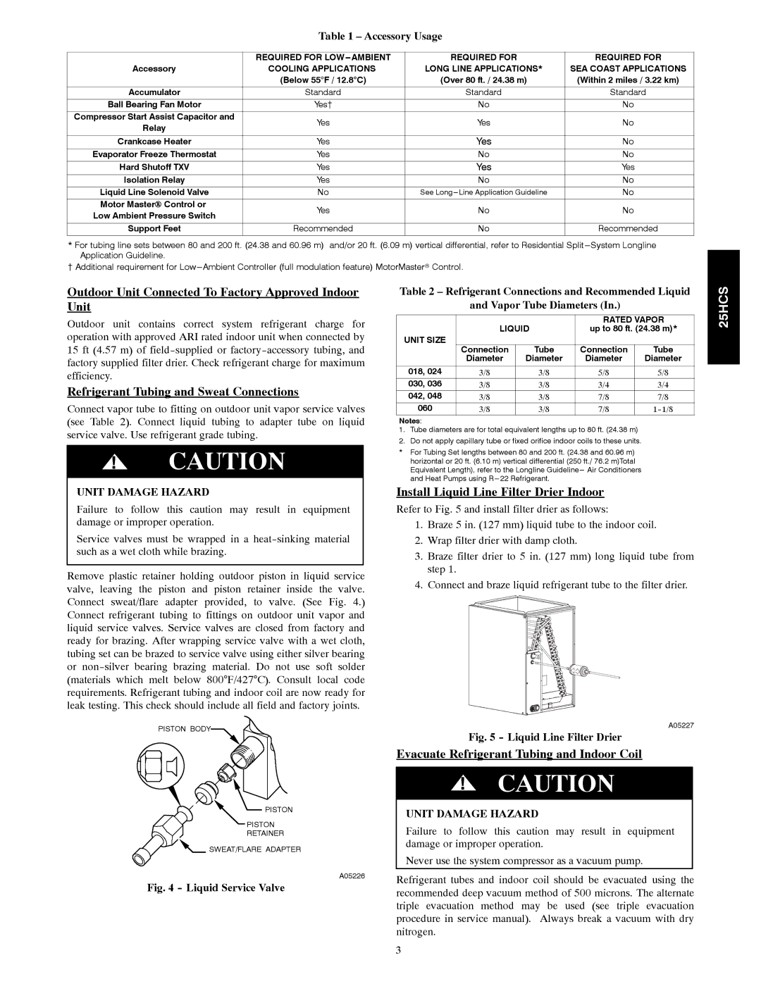
Install Liquid Line Filter Drier Indoor
Refer to Fig. 5 and install filter drier as follows:
1.Braze 5 in. (127 mm) liquid tube to the indoor coil.
2.Wrap filter drier with damp cloth.
3.Braze filter drier to 5 in. (127 mm) long liquid tube from step 1.
4.Connect and braze liquid refrigerant tube to the filter drier.
A05227
Fig. 5 - Liquid Line Filter Drier
Evacuate Refrigerant Tubing and Indoor Coil
!CAUTION
UNIT DAMAGE HAZARD
Failure to follow this caution may result in equipment damage or improper operation.
Never use the system compressor as a vacuum pump.
Refrigerant tubes and indoor coil should be evacuated using the recommended deep vacuum method of 500 microns. The alternate triple evacuation method may be used (see triple evacuation procedure in service manual). Always break a vacuum with dry nitrogen.
25HCS
3