Install HGBP/Pump Board and Control Wiring

1.Attach the solenoid coil assembly to the solenoid valve plunger on the tube assembly for each circuit. One cable assembly TH70400410 is supplied per circuit. Secure the DIN connector end on the solenoid valve coil with the screw in the connector. Verify the square rubber gasket is in place to ensure connection remains watertight.

Take care connecting leads to terminal blocks. Incorrect polarity will damage the control boards.

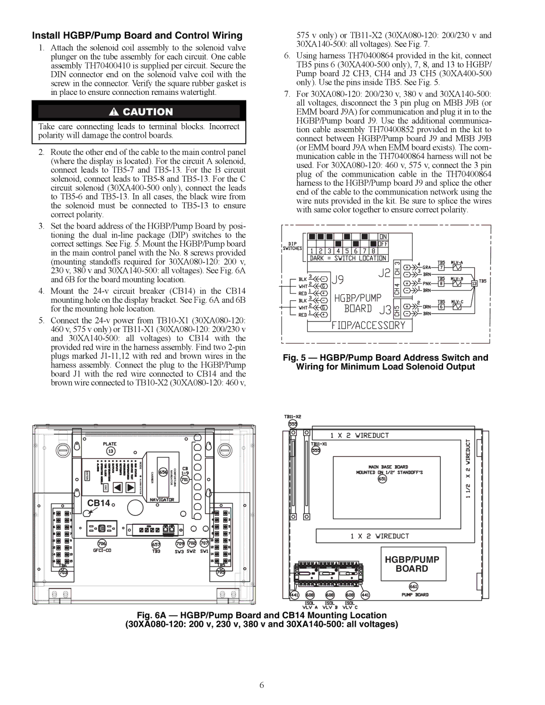
2.Route the other end of the cable to the main control panel (where the display is located). For the circuit A solenoid, connect leads to TB5-7 and TB5-13. For the B circuit solenoid, connect leads to TB5-8 and TB5-13. For the C circuit solenoid (30XA400-500 only), connect the leads to TB5-6 and TB5-13. In all cases, the black wire from the solenoid must be connected to TB5-13 to ensure correct polarity.

3.Set the board address of the HGBP/Pump Board by posi- tioning the dual in-line package (DIP) switches to the correct settings. See Fig. 5. Mount the HGBP/Pump board in the main control panel with the No. 8 screws provided (mounting standoffs required for 30XA080-120: 200 v, 230 v, 380 v and 30XA140-500: all voltages). See Fig. 6A and 6B for the board mounting location.

4.Mount the 24-v circuit breaker (CB14) in the CB14 mounting hole on the display bracket. See Fig. 6A and 6B for the mounting hole location.

5.Connect the 24-v power from TB10-X1 (30XA080-120: 460 v, 575 v only) or TB11-X1 (30XA080-120: 200/230 v and 30XA140-500: all voltages) to CB14 with the provided red wire in the harness assembly. Find two 2-pin plugs marked J1-11,12 with red and brown wires in the harness assembly. Connect the plug to the HGBP/Pump board J1 with the red wire connected to CB14 and the brown wire connected to TB10-X2 (30XA080-120: 460 v,

CB14

575 v only) or TB11-X2 (30XA080-120: 200/230 v and

30XA140-500: all voltages). See Fig. 7.

6.Using harness TH70400864 provided in the kit, connect TB5 pins 6 (30XA400-500 only), 7, 8, and 13 to HGBP/ Pump board J2 CH3, CH4 and J3 CH5 (30XA400-500 only). Use the pins inside TB5. See Fig. 5.

7.For 30XA080-120: 200/230 v, 380 v and 30XA140-500: all voltages, disconnect the 3 pin plug on MBB J9B (or EMM board J9A) for communication and plug it in to the HGBP/Pump board J9. Use the additional communica- tion cable assembly TH70400852 provided in the kit to connect between HGBP/Pump board J9 and MBB J9B (or EMM board J9A when EMM board exists). The com- munication cable in the TH70400864 harness will not be used. For 30XA080-120: 460 v, 575 v, connect the 3 pin plug of the communication cable in the TH70400864 harness to the HGBP/Pump board J9 and splice the other end of the cable to the communication network using the wire nuts provided in the kit. Be sure to splice the wires with same color together to ensure correct polarity.

a30-4503

Fig. 5 — HGBP/Pump Board Address Switch and

Wiring for Minimum Load Solenoid Output

HGBP/PUMP

BOARD

a30-4504

Fig. 6A — HGBP/Pump Board and CB14 Mounting Location

(30XA080-120: 200 v, 230 v, 380 v and 30XA140-500: all voltages)

6

Page 6
Image 6
Carrier 30XA080-500 installation instructions Install HGBP/Pump Board and Control Wiring, CB14

30XA080-500 specifications

The Carrier 30XA080-500 is a sophisticated air-cooled chiller designed for large commercial and industrial applications, renowned for its energy efficiency and reliability. This model is part of Carrier's extensive range of chillers, providing an optimal solution for space cooling needs while supporting sustainability goals.

One of the main features of the 30XA080-500 is its advanced scroll compressor technology. This design not only enhances the chiller's efficiency but also ensures quieter operation. The compressors operate with a high efficiency at partial loads, making the 30XA080-500 ideal for buildings with varying cooling demands. The unit also incorporates multiple compressors, allowing for enhanced reliability through redundancy; if one compressor fails, others can maintain performance.

The 30XA080-500 is equipped with high-performance evaporators and condensers which facilitate superior heat exchange. The unit features a fin-and-tube heat exchanger design, optimized for maximum surface area and minimal air resistance, thus enhancing overall performance. Moreover, the chiller is built with microchannel technology, which significantly reduces the refrigerant charge while improving efficiency through better heat transfer.

In terms of controls, the Carrier 30XA080-500 utilizes advanced VFD (Variable Frequency Drive) technology. This allows the system to adjust motor speed to match building loads, further increasing efficiency and reducing energy consumption. The intuitive control options enable users to monitor performance and make adjustments easily, helping optimize system operations in real time.

Another highlight of the 30XA080-500 is its environmentally conscious refrigerant, R-410A, which is known for its low Global Warming Potential (GWP). This makes the unit compliant with current and future environmental regulations, ensuring that users can operate within legal limits while reducing their carbon footprint.

The durability of the 30XA080-500 is enhanced by a rugged construction designed to withstand various weather conditions, making it suitable for outdoor installation. Insulated panels and protective coatings guard against corrosion, extending the lifespan of components and reducing maintenance costs.

In conclusion, the Carrier 30XA080-500 is a high-efficiency chiller that offers advanced technology, reliable performance, and environmental consciousness, making it an excellent choice for modern commercial buildings seeking to balance cooling needs with sustainability and energy savings. Its combination of innovative features positions it as a leader in the chiller market.