5/8 in. HEX

6" MINIMUM

CLEARANCE FOR

1/4-18 NPT

1.188 in.

WIRE TIE

INSERT THERMISTOR UNTIL

O-RING MEETS THE

THERMISTOR WELL BODY.

THERMISTOR

REMOVAL

2.315 in.

a30-3999

LOOP

THERMISTOR WIRE

AND SECURE

TO CHILLED WATER PIPE

a30-4000

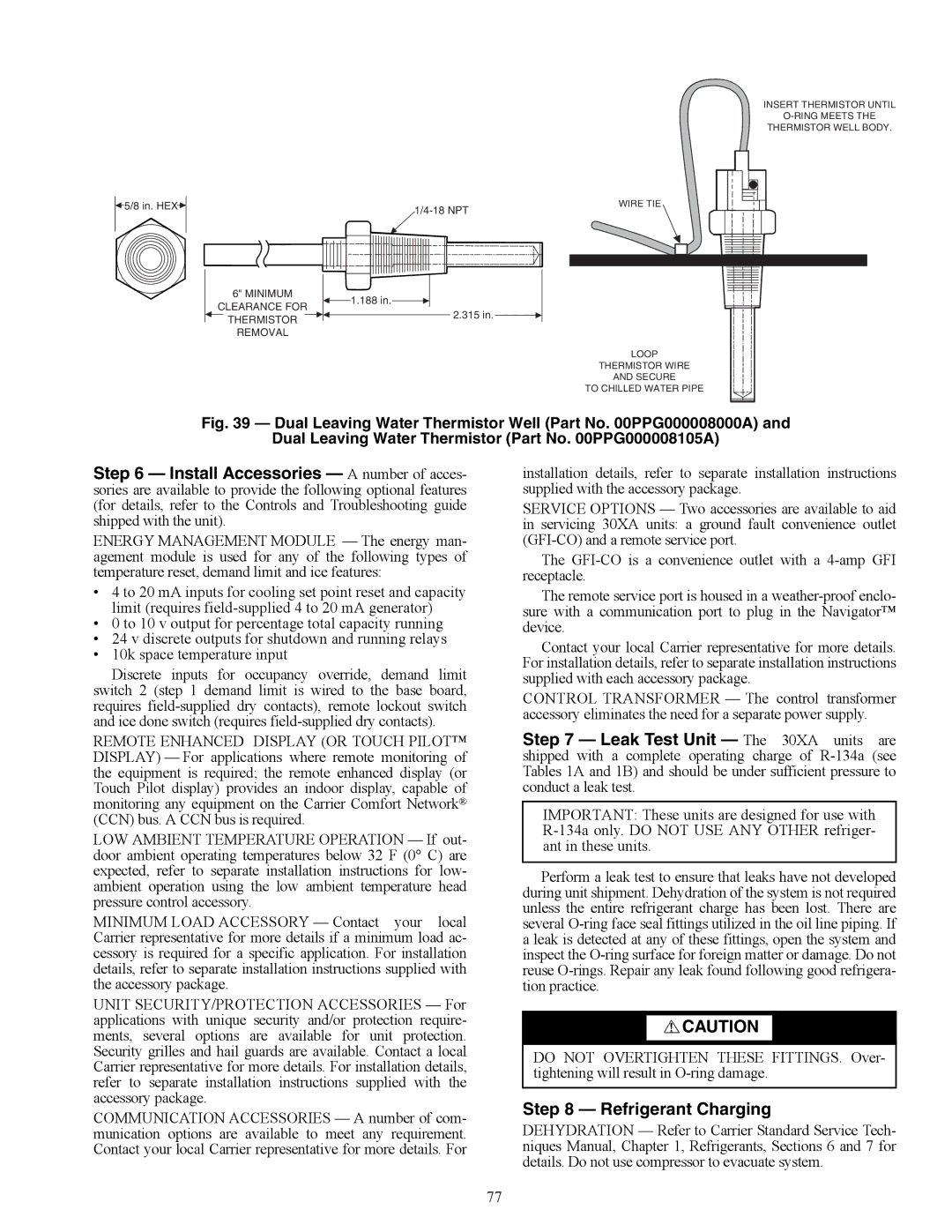
Fig. 39 — Dual Leaving Water Thermistor Well (Part No. 00PPG000008000A) and

Dual Leaving Water Thermistor (Part No. 00PPG000008105A)

Step 6 — Install Accessories — A number of acces- sories are available to provide the following optional features (for details, refer to the Controls and Troubleshooting guide shipped with the unit).

ENERGY MANAGEMENT MODULE — The energy man- agement module is used for any of the following types of temperature reset, demand limit and ice features:

4 to 20 mA inputs for cooling set point reset and capacity limit (requires field-supplied 4 to 20 mA generator)

0 to 10 v output for percentage total capacity running

24 v discrete outputs for shutdown and running relays

10k space temperature input

Discrete inputs for occupancy override, demand limit switch 2 (step 1 demand limit is wired to the base board, requires field-supplied dry contacts), remote lockout switch and ice done switch (requires field-supplied dry contacts).

REMOTE ENHANCED DISPLAY (OR TOUCH PILOT™ DISPLAY) — For applications where remote monitoring of the equipment is required; the remote enhanced display (or Touch Pilot display) provides an indoor display, capable of monitoring any equipment on the Carrier Comfort Network® (CCN) bus. A CCN bus is required.

LOW AMBIENT TEMPERATURE OPERATION — If out- door ambient operating temperatures below 32 F (0° C) are expected, refer to separate installation instructions for low- ambient operation using the low ambient temperature head pressure control accessory.

MINIMUM LOAD ACCESSORY — Contact your local Carrier representative for more details if a minimum load ac- cessory is required for a specific application. For installation details, refer to separate installation instructions supplied with the accessory package.

UNIT SECURITY/PROTECTION ACCESSORIES — For applications with unique security and/or protection require- ments, several options are available for unit protection. Security grilles and hail guards are available. Contact a local Carrier representative for more details. For installation details, refer to separate installation instructions supplied with the accessory package.

COMMUNICATION ACCESSORIES — A number of com- munication options are available to meet any requirement. Contact your local Carrier representative for more details. For

installation details, refer to separate installation instructions supplied with the accessory package.

SERVICE OPTIONS — Two accessories are available to aid in servicing 30XA units: a ground fault convenience outlet (GFI-CO) and a remote service port.

The GFI-CO is a convenience outlet with a 4-amp GFI receptacle.

The remote service port is housed in a weather-proof enclo- sure with a communication port to plug in the Navigator™ device.

Contact your local Carrier representative for more details. For installation details, refer to separate installation instructions supplied with each accessory package.

CONTROL TRANSFORMER — The control transformer accessory eliminates the need for a separate power supply.

Step 7 — Leak Test Unit — The 30XA units are shipped with a complete operating charge of R-134a (see Tables 1A and 1B) and should be under sufficient pressure to conduct a leak test.

IMPORTANT: These units are designed for use with R-134a only. DO NOT USE ANY OTHER refriger- ant in these units.

Perform a leak test to ensure that leaks have not developed during unit shipment. Dehydration of the system is not required unless the entire refrigerant charge has been lost. There are several O-ring face seal fittings utilized in the oil line piping. If a leak is detected at any of these fittings, open the system and inspect the O-ring surface for foreign matter or damage. Do not reuse O-rings. Repair any leak found following good refrigera- tion practice.

CAUTION

DO NOT OVERTIGHTEN THESE FITTINGS. Over- tightening will result in O-ring damage.

Step 8 — Refrigerant Charging

DEHYDRATION — Refer to Carrier Standard Service Tech- niques Manual, Chapter 1, Refrigerants, Sections 6 and 7 for details. Do not use compressor to evacuate system.

77

Page 77
Image 77
Carrier 30XA080-500 specifications A30-3999, A30-4000

30XA080-500 specifications

The Carrier 30XA080-500 is a sophisticated air-cooled chiller designed for large commercial and industrial applications, renowned for its energy efficiency and reliability. This model is part of Carrier's extensive range of chillers, providing an optimal solution for space cooling needs while supporting sustainability goals.

One of the main features of the 30XA080-500 is its advanced scroll compressor technology. This design not only enhances the chiller's efficiency but also ensures quieter operation. The compressors operate with a high efficiency at partial loads, making the 30XA080-500 ideal for buildings with varying cooling demands. The unit also incorporates multiple compressors, allowing for enhanced reliability through redundancy; if one compressor fails, others can maintain performance.

The 30XA080-500 is equipped with high-performance evaporators and condensers which facilitate superior heat exchange. The unit features a fin-and-tube heat exchanger design, optimized for maximum surface area and minimal air resistance, thus enhancing overall performance. Moreover, the chiller is built with microchannel technology, which significantly reduces the refrigerant charge while improving efficiency through better heat transfer.

In terms of controls, the Carrier 30XA080-500 utilizes advanced VFD (Variable Frequency Drive) technology. This allows the system to adjust motor speed to match building loads, further increasing efficiency and reducing energy consumption. The intuitive control options enable users to monitor performance and make adjustments easily, helping optimize system operations in real time.

Another highlight of the 30XA080-500 is its environmentally conscious refrigerant, R-410A, which is known for its low Global Warming Potential (GWP). This makes the unit compliant with current and future environmental regulations, ensuring that users can operate within legal limits while reducing their carbon footprint.

The durability of the 30XA080-500 is enhanced by a rugged construction designed to withstand various weather conditions, making it suitable for outdoor installation. Insulated panels and protective coatings guard against corrosion, extending the lifespan of components and reducing maintenance costs.

In conclusion, the Carrier 30XA080-500 is a high-efficiency chiller that offers advanced technology, reliable performance, and environmental consciousness, making it an excellent choice for modern commercial buildings seeking to balance cooling needs with sustainability and energy savings. Its combination of innovative features positions it as a leader in the chiller market.