Carrier 30XA080-500 specifications Pump Electrical Data, CCN Communication Bus Wiring, A30-4001

Models: 30XA080-500

1 80
Download 80 pages 61.28 Kb
Page 76
Image 76

Table 11 — Pump Electrical Data

PUMP

UNIT VOLTAGE

HYDRONIC SYSTEM (SINGLE OR DUAL)

30XA

HP

V-Hz (3 Ph)

FLA (Each)

UNIT SIZE


230-60

11.6


5

200-60

12.6


460-60

5.8

090-160


575-60

4.6


380-60

7.0


230-60

17.4


7.5

200-60

18.5


460-60

8.7

090-160


575-60

7.0


380-60

10.4


230-60

23.0


10

200-60

25.0


460-60

11.5

090-160


575-60

9.2


380-60

14.0


230-60

34.0


15

200-60

36.7


460-60

17.0

090-160


575-60

14.0


380-60

21.0


FLA — Full Load Amps

Table 12 — CCN Communication Bus Wiring

MANUFACTURER

PART NUMBER

Regular Wiring

Plenum Wiring


Alpha

1895

American

A21451

A48301

Belden

8205

884421

Columbia

D6451

Manhatten

M13402

M64430

Quabik

6130

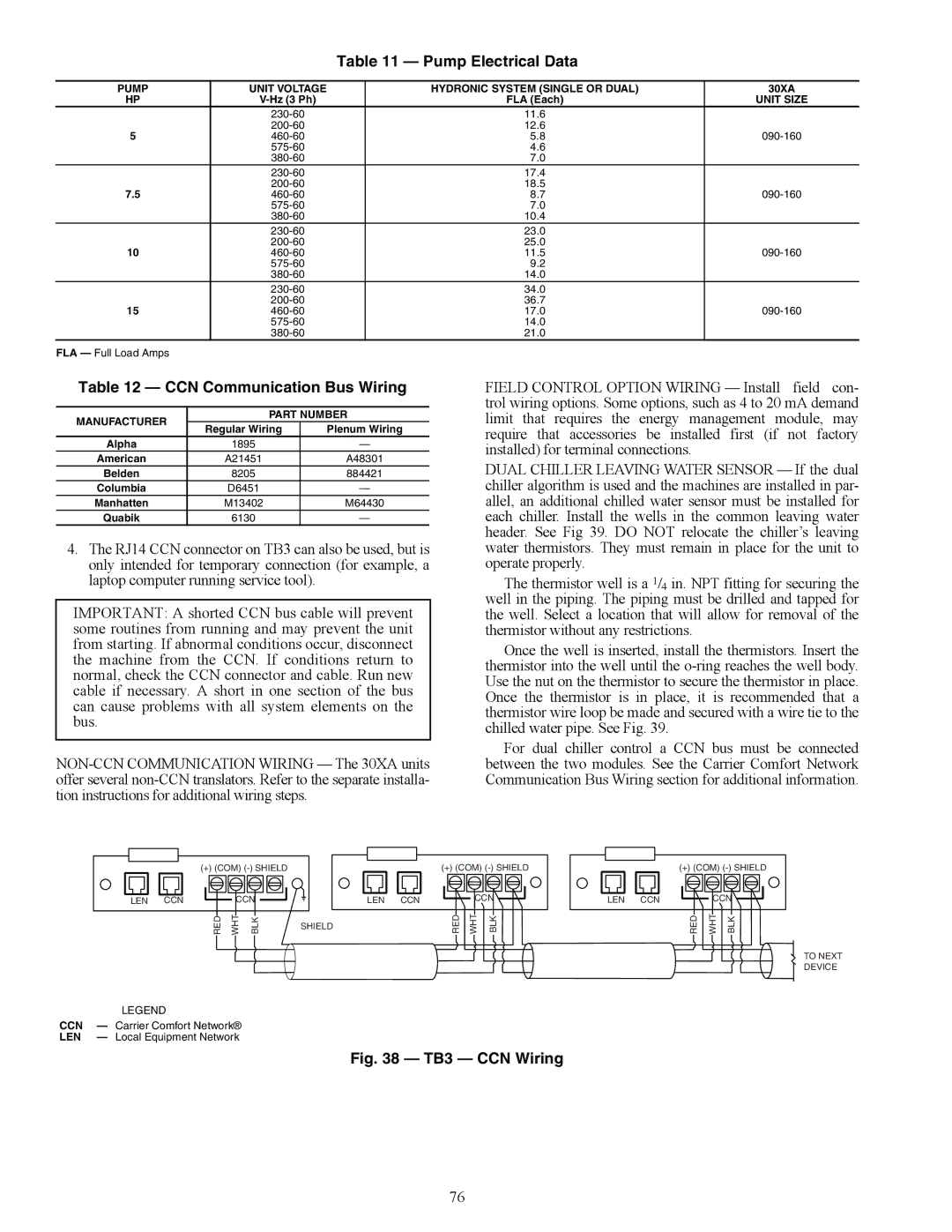
4.The RJ14 CCN connector on TB3 can also be used, but is only intended for temporary connection (for example, a laptop computer running service tool).

IMPORTANT: A shorted CCN bus cable will prevent some routines from running and may prevent the unit from starting. If abnormal conditions occur, disconnect the machine from the CCN. If conditions return to normal, check the CCN connector and cable. Run new cable if necessary. A short in one section of the bus can cause problems with all system elements on the bus.

NON-CCN COMMUNICATION WIRING — The 30XA units offer several non-CCN translators. Refer to the separate installa- tion instructions for additional wiring steps.

FIELD CONTROL OPTION WIRING — Install field con- trol wiring options. Some options, such as 4 to 20 mA demand limit that requires the energy management module, may require that accessories be installed first (if not factory installed) for terminal connections.

DUAL CHILLER LEAVING WATER SENSOR — If the dual chiller algorithm is used and the machines are installed in par- allel, an additional chilled water sensor must be installed for each chiller. Install the wells in the common leaving water header. See Fig 39. DO NOT relocate the chiller’s leaving water thermistors. They must remain in place for the unit to operate properly.

The thermistor well is a 1/4 in. NPT fitting for securing the well in the piping. The piping must be drilled and tapped for the well. Select a location that will allow for removal of the thermistor without any restrictions.

Once the well is inserted, install the thermistors. Insert the thermistor into the well until the o-ring reaches the well body. Use the nut on the thermistor to secure the thermistor in place. Once the thermistor is in place, it is recommended that a thermistor wire loop be made and secured with a wire tie to the chilled water pipe. See Fig. 39.

For dual chiller control a CCN bus must be connected between the two modules. See the Carrier Comfort Network Communication Bus Wiring section for additional information.

(+) (COM) (-) SHIELD

(+) (COM) (-) SHIELD


LEN

CCN

CCN

LEN

CCN

CCN

LEN

CCN

RED

WHT

BLK

SHIELD

RED

WHT

BLK


a30-4001

LEGEND

CCN — Carrier Comfort Network®

LEN — Local Equipment Network

Fig. 38 — TB3 — CCN Wiring

(+)(COM) (-) SHIELD CCN

RED

WHT

BLK

TO NEXT DEVICE

76

Page 76
Image 76
Carrier 30XA080-500 specifications Pump Electrical Data, CCN Communication Bus Wiring, A30-4001

30XA080-500 specifications

The Carrier 30XA080-500 is a sophisticated air-cooled chiller designed for large commercial and industrial applications, renowned for its energy efficiency and reliability. This model is part of Carrier's extensive range of chillers, providing an optimal solution for space cooling needs while supporting sustainability goals.

One of the main features of the 30XA080-500 is its advanced scroll compressor technology. This design not only enhances the chiller's efficiency but also ensures quieter operation. The compressors operate with a high efficiency at partial loads, making the 30XA080-500 ideal for buildings with varying cooling demands. The unit also incorporates multiple compressors, allowing for enhanced reliability through redundancy; if one compressor fails, others can maintain performance.

The 30XA080-500 is equipped with high-performance evaporators and condensers which facilitate superior heat exchange. The unit features a fin-and-tube heat exchanger design, optimized for maximum surface area and minimal air resistance, thus enhancing overall performance. Moreover, the chiller is built with microchannel technology, which significantly reduces the refrigerant charge while improving efficiency through better heat transfer.

In terms of controls, the Carrier 30XA080-500 utilizes advanced VFD (Variable Frequency Drive) technology. This allows the system to adjust motor speed to match building loads, further increasing efficiency and reducing energy consumption. The intuitive control options enable users to monitor performance and make adjustments easily, helping optimize system operations in real time.

Another highlight of the 30XA080-500 is its environmentally conscious refrigerant, R-410A, which is known for its low Global Warming Potential (GWP). This makes the unit compliant with current and future environmental regulations, ensuring that users can operate within legal limits while reducing their carbon footprint.

The durability of the 30XA080-500 is enhanced by a rugged construction designed to withstand various weather conditions, making it suitable for outdoor installation. Insulated panels and protective coatings guard against corrosion, extending the lifespan of components and reducing maintenance costs.

In conclusion, the Carrier 30XA080-500 is a high-efficiency chiller that offers advanced technology, reliable performance, and environmental consciousness, making it an excellent choice for modern commercial buildings seeking to balance cooling needs with sustainability and energy savings. Its combination of innovative features positions it as a leader in the chiller market.