FILL CONDENSER WITH


CLEANING SOLUTION. DO

PAIL

NOT ADD SOLUTION


MORE RAPIDLY THAN


VENT CAN EXHAUST


GASES CAUSED BY

FUNNEL

CHEMICAL ACTION.


1”


PIPE

VENT


PIPE

5’ APPROX


3’ TO 4’

CONDENSER

PAIL

Fig. 8 — Gravity Flow Method

PUMP

PRIMING

GAS VENT


CONN.

GLOBE


VALVES

SUCTION


PUMP


SUPPLY


SUPPORT


1” PIPE


CONDENSER

TANK


REMOVE WATER


REGULATING VALVE

FINE MESH


RETURN

SCREEN


Fig. 9 — Forced Circulation Method

Checking System Charge — Units are shipped with full operating charge. If recharging is necessary:

1.Insert thermometer bulb in insulating rubber sleeve on liquid line near filter drier. Use a digital thermometer for all temperature measurements. DO NOT use a mercury or dial-type thermometer.

2.Connect pressure gage to discharge line near compressor.

3.After unit conditions have stabilized, read head pressure on discharge line gage.

NOTE: Operate unit a minimum of 15 minutes before checking charge.

4.From standard field-supplied Pressure-Temperature chart for R-22, find equivalent saturated condensing temperature.

5.Read liquid line temperature on thermometer; then subtract from saturated condensing temperature. The dif- ference equals subcooling temperature.

6.ADD refrigerant to raise the temperature or REMOVE refrigerant (using standard practices) to lower the temper- ature (allow a tolerance of ± 3° F), as required.

Refrigerant Charging

To prevent personal injury, wear safety glasses and gloves when handling refrigerant. Do not overcharge system — this can cause compressor flooding.

NOTE: Do not vent or depressurize unit refrigerant to atmo- sphere. Remove and reclaim refrigerant following accepted practices.

Air Coil Fan Motor Removal

Before attempting to remove fan motors or motor mounts, place a piece of plywood over evaporator coils to prevent coil damage.

Motor power wires need to be disconnected from motor terminals before motor is removed from unit.

1.Shut off unit main power supply.

2.Loosen bolts on mounting bracket so that fan belt can be removed.

3.Loosen and remove the 2 motor mounting bracket bolts on left side of bracket.

4.Slide motor/bracket assembly to extreme right and lift out through space between fan scroll and side frame. Rest motor on a high platform such as a step ladder. Do not allow motor to hang by its power wires.

TROUBLESHOOTING

(Fig. 10 and 11, and Table 22)

When troubleshooting problems with a WSHP, consider the following.

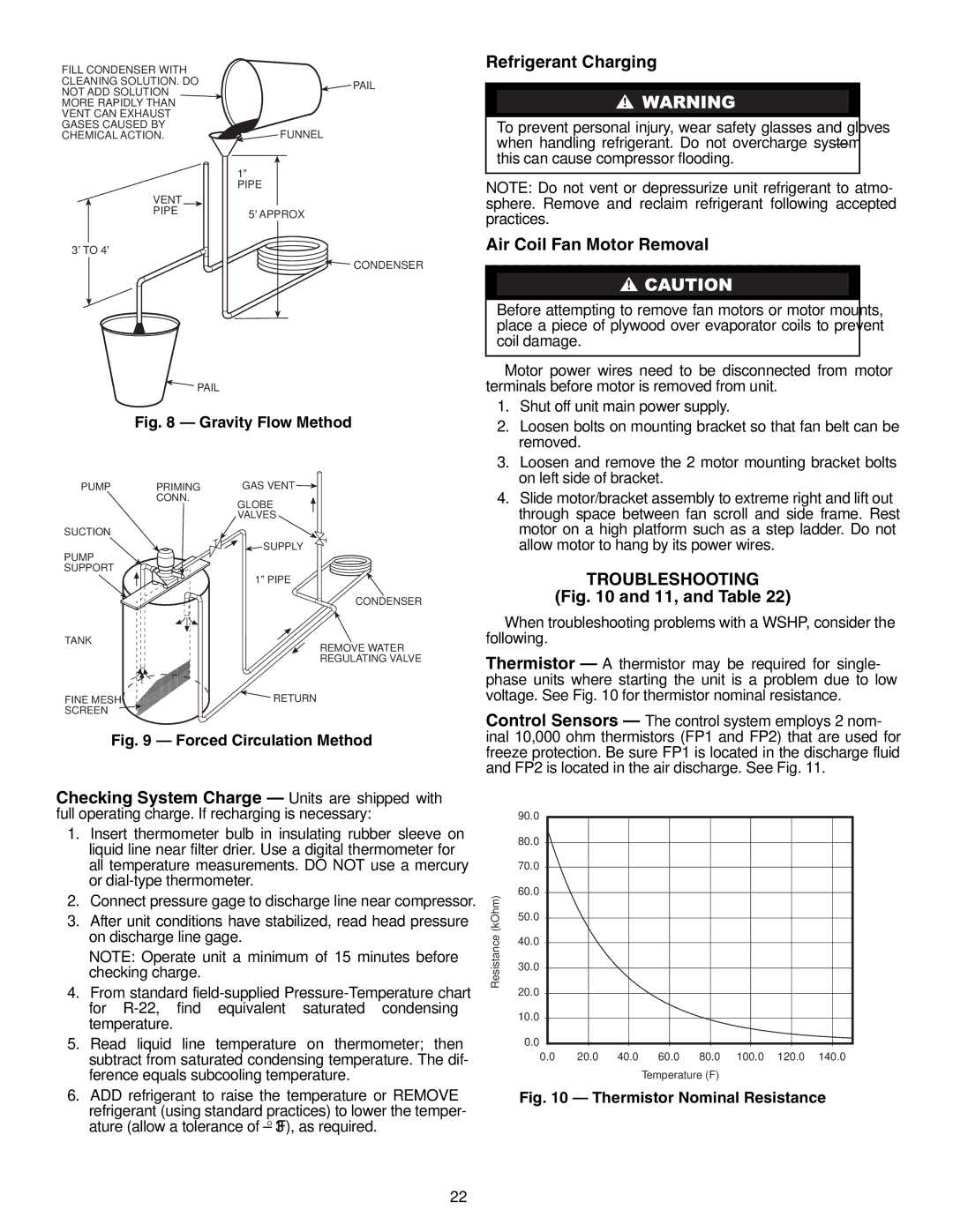
Thermistor — A thermistor may be required for single- phase units where starting the unit is a problem due to low voltage. See Fig. 10 for thermistor nominal resistance.

Control Sensors — The control system employs 2 nom- inal 10,000 ohm thermistors (FP1 and FP2) that are used for freeze protection. Be sure FP1 is located in the discharge fluid and FP2 is located in the air discharge. See Fig. 11.


90.0


80.0


70.0


(kOhm)

60.0


50.0


Resistance


40.0


30.0


20.0


10.0


0.0


0.0

20.0

40.0

60.0

80.0

100.0

120.0

140.0


Temperature (F)


Fig. 10 — Thermistor Nominal Resistance

22

Page 22
Image 22
Carrier 50RTG specifications Refrigerant Charging, Air Coil Fan Motor Removal, Troubleshooting

50RTG specifications

The Carrier 50RTG represents a significant advancement in the field of rooftop air conditioning systems, combining performance, efficiency, and reliability for commercial applications. Designed to meet the rigorous demands of today’s buildings, the 50RTG series is ideally suited for a variety of environments, including retail, office spaces, and industrial facilities.

One of the standout features of the Carrier 50RTG is its energy efficiency. Utilizing the latest in compressor technology, these units achieve high Seasonal Energy Efficiency Ratios (SEER) and Energy Efficiency Ratios (EER), which translates to lower energy costs for users. This efficiency is further enhanced by the incorporation of environmentally friendly refrigerants that comply with current regulations, reducing the overall carbon footprint of the unit.

Another notable characteristic of the 50RTG series is its modular design. The unit can be tailored to specific requirements, making it versatile for different installation scenarios. This modularity not only simplifies maintenance and repair operations but also allows for easy upgrades as technologies evolve or as space demands change.

The advanced control system in the 50RTG is another key technology that sets it apart from competing products. Intuitive user interfaces and smart controls enable precise temperature regulation and improved energy management. These controls often include features such as variable speed fans and integrated economizers, which optimize the system's performance in real-time based on current load requirements.

Durability is also a hallmark of the Carrier 50RTG. Constructed with robust materials and designed to withstand harsh weather conditions, these units provide dependable operation year-round. The corrosion-resistant finish and weather-tight construction ensure that the systems maintain their performance levels and aesthetic appeal over time.

Additionally, the 50RTG series is designed with a focus on low noise operation. With quieter components and advanced noise control technology, these units are ideal for noise-sensitive environments, ensuring that occupants can work, live, or shop in comfort without disruptive background noise.

In summary, the Carrier 50RTG series exemplifies the perfect combination of energy efficiency, advanced technology, customization potential, durability, and low noise operation, making it a top choice for commercial heating and cooling needs. Its innovative features and reliable performance solidify its status as a leader in rooftop HVAC solutions, catering to the evolving requirements of modern buildings.