A95464


GV


DSS


PRS


L1

L2

TO 115V AC FIELD DISCONNECTIONS

SCHEMATIC

CONNECTION DIAGRAM


MGV


TR


TH

BRN


NO

C

ILK


NOTE #4


DIAGRAM


PILOT


NC


EQUIPMENT GROUND


LO


L1


L1


SPARE-2


HFR

CFR


MED LO


ALS


FL


LS


HEAT


MED HI


NOTE #9


SPARE-1


HI


START


OL


(WHEN USED)


COOL


CAP


IDM


NOTE #6


COM


COM


BLWM


WHT


EAC-1


BLK


IDR

EAC-2

PL1-3


IDM


RED


PL1-1


BLU


FUSED DISCONNECT

NOTE #4

WHT

TRAN


115V AC

ILK


SWITCH (WHEN REQ'D)


LS

FL

ALS

PL1-4

FU1

PR-1

TRAN

PR-2


BLK


BLK


WHT


WHT


PL1-7


3A

SEC-1 24V AC

SEC-2


FU2


WHT


BLK

BLK

BLU RED

BLK

RED RED

BLU

BRN ORN

YEL


FUSE


(WHEN USED)


NOTE #7


WHT

GRN


COM


NOTE #6


HFR


PL1

1

4

7


GRN


JB

PR2 L2


L1

PR1


2

5

8


R


LOGIC


CFR


HFR


PL1-9


EAC-2


3

6

9


TIME


LO


GRN

BLWM

WHT (COM)


DELAY


EAC-1

HI


BRN


BLK (HI)


DSS


MGV

GV

PL1-8


OL

SPARE-1


Y


CAP


YEL (MED HI)


NOTE #9


IDR

RED


PRS


TH


TR


START

SPARE-2


NO

C


PILOT


BLU

SEC-2


NC


BLU (MED LO)


BRN


RED (LO)


SEC-1


PL1-6

IDR

PL1-2


FU1


W

Y

R

C

G


3AMP

GROUND

W


FUSE

SCREW


PCB


NOTE #7

REQUIRED


IDR


CFR


NOTE #8


NOTE #1

G


NOTE #9


LEGEND


C


ALS

AUXILIARY LIMIT SWITCH, OVERTEMP.


JUNCTION


-MANUAL RESET, SPST-(N.C.)


UNMARKED TERMINAL


BLWM

BLOWER MOTOR


NOTES:


CAP

CAPACITOR


PCB TERMINAL


CFR

COOLING FAN RELAY, SPDT


FACTORY POWER WIRING (120 AC)

1. Internally connected to equipment ground through mounting screw.


DSS

DRAFT SAFEGUARD SWITCH, SPST-(N.C.),


2.

If any of the original equipment wire is replaced, use wire rated for 105°C.


MANUAL RESET


FACTORY CONTROL WIRING (120 AC)


EAC-1 ELECTRONIC AIR CLEANER CONNECTION (115 VAC)


3. Blower motor (BLWM) & Inducer motor (IDM) contain auto-reset


EAC-2 ELECTRONIC AIR CLEANER CONNECTION (COMMON)


FIELD POWER WIRING (120 AC)


thermal overload switch.


FL

FUSIBLE LINK


CONDUCTOR ON PCB


4.

Use only copper wire between the disconnect switch and the furnace


FU1

FUSE, 3 AMP, AUTOMOTIVE BLADE TYPE


FU2

FUSE FIELD INSTALLED


FIELD WIRING SCREW TERMINAL


junction box (JB).


GV

GAS VALVE-REDUNDANT OPERATORS


5.

Symbols are electrical representations only6.


HFR

HEATING FAN RELAY, SPST (N.O.)


FIELD GROUND


IDM

INDUCED DRAFT MOTOR


EQUIPMENT GROUND


6. Auxiliary limit switch (ALS) used on downflow models only.


IDR

INDUCED DRAFT RELAY, SPST-(N.O.)


7.

The transformer 24VAC winding is protected by a 3 AMP automotive


ILK

BLOWER ACCESS PANEL INTERLOCK SWITCH,


FIELD SPLICE


blade type fuse on the control board. A 24VAC short to ground during


SPST-(N.O.)


PLUG RECEPTACLE


JB

JUNCTION BOX


installation, checkout, operation, service or maintenance could cause


LS

LIMIT SWITCH, AUTO RESET, SPST(N.C.)


this fuse to open. Do not replace the 3 AMP fuse with any other size fuse.

OL

AUTO-RESET INTERNAL MOTOR OVERLOAD TEMP. SW.


PCB

PRINTED CIRCUIT BOARD (FURNACE CONTROL)


8.

Blower motor (BLWM) adjustable OFF-DELAY. Factory set: 120 seconds

PL1

9-CIRCUIT CONNECTOR (PCB1)


cut resistor: 180 seconds.


PR5

PRESSURE SWITCH, SPDT


9.

When CFR relay is energized, HFR relay is also energized.


TRAN

TRANSFORMER (115V AC/24V AC)


322876-101 REV. A

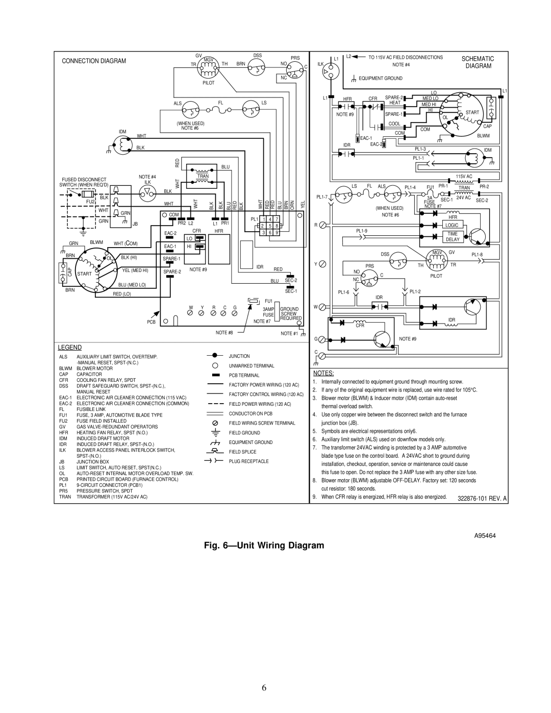
Fig. 6ÐUnit Wiring Diagram

6

Page 6
Image 6
Carrier 58GFA instruction manual ÐUnit Wiring Diagram

58GFA specifications

The Carrier 58GFA is a highly regarded gas furnace known for its reliability, energy efficiency, and advanced technology. Designed with the modern homeowner in mind, the 58GFA is engineered to provide effective heating while minimizing energy consumption and operating costs.

One of the standout features of the Carrier 58GFA is its variable-speed blower motor. This technology allows for enhanced airflow control, ensuring consistent temperatures throughout the home. The variable-speed operation enables the furnace to adjust its output based on the heating demands, which not only improves comfort but also increases energy efficiency by running at lower speeds for extended periods.

Another key characteristic of the 58GFA is its two-stage heating system. This dual-stage capability allows the furnace to operate at a lower stage during milder conditions, optimizing energy usage without sacrificing comfort. During peak heating demands, the system can seamlessly transition to full capacity. This feature reduces temperature fluctuations, providing a more stable indoor climate.

The Carrier 58GFA is equipped with high-efficiency burners, achieving impressive Annual Fuel Utilization Efficiency (AFUE) ratings. With an AFUE rating of up to 80%, this furnace competently converts fuel into heat, making it an economical choice for homeowners looking to reduce energy bills. Additionally, the unit complies with environmental standards, contributing to a greener home footprint.

Durability and quiet operation are also notable characteristics of the Carrier 58GFA. The within design includes a robust heat exchanger made of high-quality materials to withstand the rigors of daily use. The noise-reducing technology, including insulated cabinets and quiet motors, ensures that the heating operation remains unobtrusive, maintaining a peaceful home environment.

Moreover, the 58GFA features advanced thermostat compatibility, allowing for integration with smart home systems. This capability allows homeowners to monitor and control their heating system remotely, enhancing convenience and energy management.

In summary, the Carrier 58GFA gas furnace is a leading choice for homeowners seeking energy-efficient heating solutions. With its variable-speed blower, two-stage heating, high AFUE rating, durable construction, and smart compatibility, it stands out as a formidable option in the HVAC market, delivering comfort and performance year after year.