Manuals
/
Exmark
/
Lawn and Garden
/
Lawn Mower
Exmark
Turf Tracer HP
manual
Wiring Diagrams
Models:
Turf Tracer HP
1
44
48
48
Download
48 pages
36.98 Kb
41
42
43
44
45
46
47
48
Troubleshooting
Specifications
Install
Grease Lubrication Chart
Safety Alert Symbol
Dimension
Maintenance
Problem
Adjustments
Safety
Page 44
Image 44
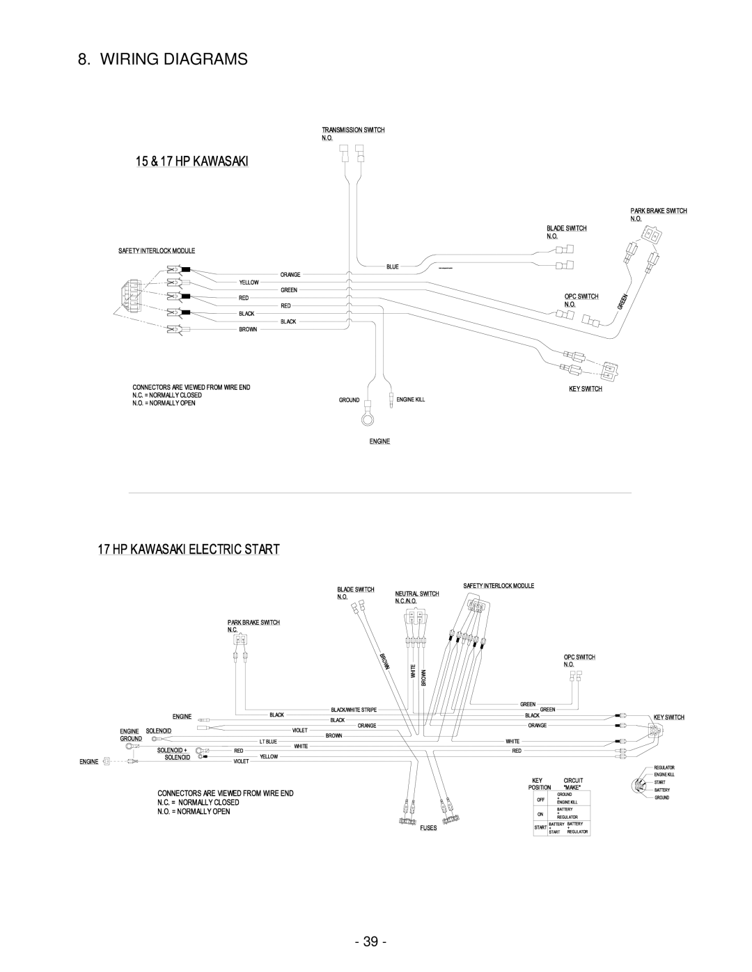
8. WIRING DIAGRAMS
- 39 -
Page 43
Page 45
Page 44
Image 44
Page 43
Page 45
Contents
For Serial Nos 440,000 & Higher
Potential Hazard
Exmark Parts Plus Program
Operators Manual
Table of Contents Safety
Specifications
Assembly Instructions
Maintenance & Adjustments
Safety
Your Safety is Involved
Safety Alert Symbol
Training
Carbon monoxide can kill you
Operation
Potential Hazard
Page
Maintenance and Storage
Safety Signs
Riding Attachments
Page
Page
Page
Specifications
Torque Requirements
Assembly Instructions
Dimensions
Machine is shipped with a filled lead acid battery
Upper Handle Mounting
Throttle Cable HOOK-UP
PTO Engagement Linkage
ECS Handles Drive Lever Linkage Installation
Service Hydraulic OIL
Operation Instructions
Drive LEVER, Neutral Lock Latch Operation
Off-Run Switch 15 & 17 HP Kawasaki Manual Start only
Pre-Start
Operating Instructions
Potential Hazard
Rotating blades under the mower deck are dangerous
Transporting
Maintenance & Adjustments
Periodic Maintenance
Potential Hazard
Blade Bolt Installation
Service Interval After First 250 hrs, then yearly thereafter
Page
Charge Pump Location
Grease Lubrication Chart
Spray Lubricant Chart
Page
Adjustments
Page
Neutral Safety Switch Adjustment
Blade Engagement Linkage
Hydro Drive Linkage Adjustment
Hydro Control LINK/SWIVEL Adjustment
Drive Lever and Latch in Neutral Position
Motor OIL Disposal
Hydro Pump Spring Tension Setting
Waste Disposal
Trouble Shooting
Battery Disposal
Mower Tracks to Left or Right
Mower Cuts Unevenly
Problem
Engine Troubleshooting
Engine Troubleshooting Table
Wiring Diagrams
Hydraulic Diagram
Limited Warranty Exmark Turf Equipment
Fold Along Appropriate Line
See EXMARK’S Complete Line of Products for Turf Care
ALL Rights Reserved
Top
Page
Image
Contents