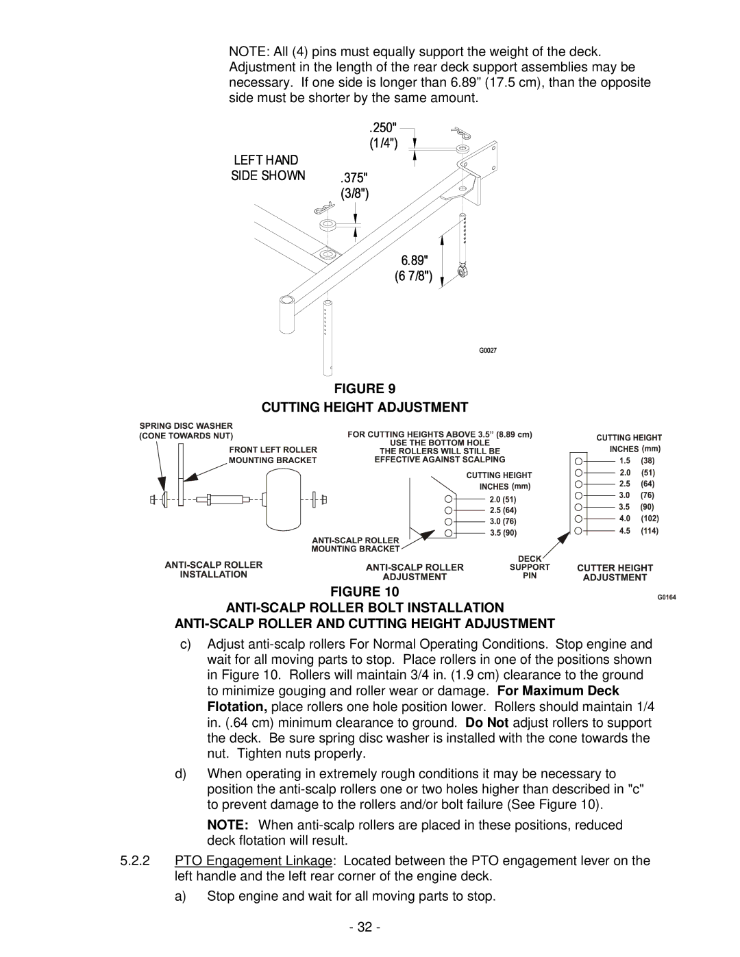
NOTE: All (4) pins must equally support the weight of the deck. Adjustment in the length of the rear deck support assemblies may be necessary. If one side is longer than 6.89” (17.5 cm), than the opposite side must be shorter by the same amount.
FIGURE 9
CUTTING HEIGHT ADJUSTMENT
FIGURE 10
ANTI-SCALP ROLLER BOLT INSTALLATION
ANTI-SCALP ROLLER AND CUTTING HEIGHT ADJUSTMENT
c)Adjust anti-scalp rollers For Normal Operating Conditions. Stop engine and wait for all moving parts to stop. Place rollers in one of the positions shown in Figure 10. Rollers will maintain 3/4 in. (1.9 cm) clearance to the ground to minimize gouging and roller wear or damage. For Maximum Deck Flotation, place rollers one hole position lower. Rollers should maintain 1/4 in. (.64 cm) minimum clearance to ground. Do Not adjust rollers to support the deck. Be sure spring disc washer is installed with the cone towards the nut. Tighten nuts properly.
d)When operating in extremely rough conditions it may be necessary to position the anti-scalp rollers one or two holes higher than described in "c" to prevent damage to the rollers and/or bolt failure (See Figure 10).
NOTE: When anti-scalp rollers are placed in these positions, reduced deck flotation will result.
5.2.2PTO Engagement Linkage: Located between the PTO engagement lever on the left handle and the left rear corner of the engine deck.
a)Stop engine and wait for all moving parts to stop.
-32 -