3.19Follow
NOTE: After starting the engine and engaging the hydro drive, if either of the drive wheels acts sluggish or will not rotate at all, stop engine and refer to Section 5.1.10 on the Hydraulic System Air Purge procedure.
3.20Perform any needed adjustments as outlined in the Adjustment Section.
4.OPERATION INSTRUCTIONS
4.1Controls
4.1.1Familiarize yourself with the controls and operation of the unit.
Carefully read the following information about the controls and their operation.
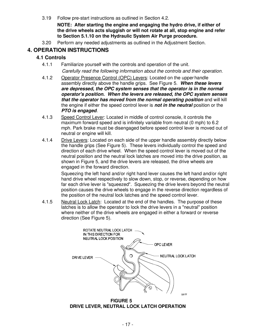
4.1.2Operator Presence Control (OPC) Levers: Located on the upper handle assembly directly above the handle grips. See Figure 5. When these levers are depressed, the OPC system senses that the operator is in the normal operator's position. When the levers are released, the OPC system senses that the operator has moved from the normal operating position and will kill the engine if either the speed control lever is not in the neutral position or the PTO is engaged.
4.1.3Speed Control Lever: Located in middle of control console, it controls the maximum forward speed and is infinitely variable from neutral (0 mph) to 6.2 mph. Park brake must be disengaged before speed control lever is moved out of neutral or engine will kill.
4.1.4Drive Levers: Located on each side of the upper handle assembly directly below the handle grips (See Figure 5). These levers individually control the speed and direction of each drive wheel. When the speed control lever is moved out of the neutral position and the neutral lock latches are moved into the drive position, as shown in Figure 5, and the drive levers are released, the drive wheels are engaged in the forward direction.
Squeezing the left hand and/or right hand lever causes the left hand and/or right hand drive wheel respectively to slow down, stop, or reverse, depending on how far each drive lever is "squeezed". Squeezing the drive levers beyond the neutral position causes the drive wheels to engage in the reverse direction regardless of the position of the neutral lock latches and the speed control lever.
4.1.5Neutral Lock Latch: Located at the end of the handles. The purpose of these latches is to allow the operator to lock the drive levers in a "neutral" position where neither of the drive wheels are engaged in either a forward or reverse direction (See Figure 5).
FIGURE 5
DRIVE LEVER, NEUTRAL LOCK LATCH OPERATION
- 17 -