Pin assignment of COMPUTER IN, MONITOR OUT connector
CONTENTS | 90 |
COMPUTER IN 1 |
| COMPUTER IN 2 |
|
| |||
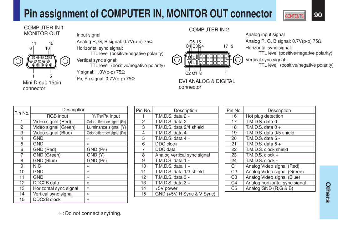
MONITOR OUT | Input signal |
| Analog input signal | ||||
|
|
| |||||
|
| Ω | C5 16 |
|
| Analog R, G, B signal: | |
11 | 15 | Analog R, G, B signal: |
|
|
| ||
Horizontal sync signal: | C4 C3 24 | 17 | 9 | Horizontal sync signal: | |||
6 | 10 | ||||||
|
|
| |||||
|
| TTL level (positive/negative polarity) |
|
|
| TTL level (positive/negative polarity) | |
|
| Vertical sync signal: |
|
|
| Vertical sync signal: | |
|
| TTL level (positive/negative polarity) |
|
|
| TTL level (positive/negative polarity) | |
1 | 5 | Y signal: | C2 C1 8 | 1 |
|
| |
PB, PR signal: |
|
| |||||
DVI ANALOG & DIGITAL |
| ||||||
Mini |
| ||||||
|
| ||||||
connector |
| connector |
|
|
| ||
Pin No. | Description |
| |
|
|
| |
RGB input |
| Y/PB/PR input | |
|
| ||
1 | Video signal (Red) |
| Color difference signal (PR) |
2 | Video signal (Green) |
| Luminance signal (Y) |
3 | Video signal (Blue) |
| Color difference signal (PB) |
4 | GND |
| * |
5 | GND |
| * |
6 | GND (Red) |
| GND (PR) |
7 | GND (Green) |
| GND (Y) |
8 | GND (Blue) |
| GND (PB) |
9 | N.C |
| * |
10 | GND |
| * |
11 | GND |
| * |
12 | DDC2B data |
| * |
13 | Horizontal sync signal |
| * |
14 | Vertical sync signal |
| * |
15 | DDC2B clock |
| * |
*: Do not connect anything.
Pin No. | Description |
1 | T.M.D.S. data 2 - |
2 | T.M.D.S. data 2 + |
3 | T.M.D.S. data 2/4 shield |
4 | T.M.D.S. data 4 - |
5 | T.M.D.S. data 4 + |
6 | DDC clock |
7 | DDC data |
8 | Analog vertical sync signal |
9 | T.M.D.S. data 1 - |
10 | T.M.D.S. data 1 + |
11 | T.M.D.S. data 1/3 shield |
12 | T.M.D.S. data 3 - |
13 | T.M.D.S. data 3 + |
14 | +5V power |
15 | GND (+5V, H Sync & V Sync) |
Pin No. | Description |
16 | Hot plug detection |
17 | T.M.D.S. data 0 - |
18 | T.M.D.S. data 0 + |
19 | T.M.D.S. data 0/5 shield |
20 | T.M.D.S. data 5 - |
21 | T.M.D.S. data 5 + |
22 | T.M.D.S. clock shield |
23 | T.M.D.S. clock + |
24 | T.M.D.S. clock - |
C1 | Analog Video signal (Red) |
C2 | Analog Video signal (Green) |
C3 | Analog Video signal (Blue) |
C4 | Analog horizontal sync signal |
C5 | Analog GND (R,G & B) |
Others