SECTION 1
DISASSEMBLY
1.1 Disassembly flow chart
This flowchart lists the disassembling steps for the cabinet parts and P.C. boards in order to gain access to item(s) to be serviced. When reassembling, perform the step(s) in reverse order. Bend, route and dress the flat cables as they were originally laid.
[1] | Top cover | |
|
|
|
[2]SW board assembly, Front panel assembly
[3]Cassette housing assembly
[4] | Drum assembly | |
|
|
|
[5]Mechanism assembly
[6]Main board assembly
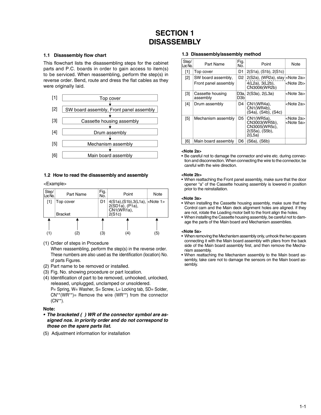
1.2How to read the disassembly and assembly
<Example>
Step/ | Part Name | Fig. | Point | Note | ||||||
LocNo. | No. | |||||||||
|
|
|
|
|
| |||||
[1] | Top cover | D1 | 4(S1a),(S1b),3(L1a), | <Note 1> | ||||||
|
|
|
|
|
| 2(SD1a), (P1a), |
|
| ||
|
|
|
|
|
| CN1(WR1a), |
|
| ||
|
| Bracket |
|
| 2(S1c) |
|
| |||
|
|
|
|
|
|
|
|
|
| |
|
|
|
|
|
|
|
|
|
| |
(1) | (2) | (3) | (4) | (5) | ||||||
(1)Order of steps in Procedure
When reassembling, perform the step(s) in the reverse order. These numbers are also used as the identification (location) No. of parts Figures.
(2)Part name to be removed or installed.
(3)Fig. No. showing procedure or part location.
(4)Identification of part to be removed, unhooked, unlocked, released, unplugged, unclamped or unsoldered.
P= Spring, W= Washer, S= Screw, L= Locking tab, SD= Solder, CN**(WR**)= Remove the wire (WR**) from the connector (CN**).
Note:
•The bracketed ( ) WR of the connector symbol are as- signed nos. in priority order and do not correspond to those on the spare parts list.
(5) Adjustment information for installation
1.3 Disassembly/assembly method
Step/ | Part Name | Fig. | Point | Note | |
LocNo. | No. | ||||
|
|
| |||
[1] | Top cover | D1 | 2(S1a), (S1b), 2(S1c) |
| |
|
|
|
|
| |
[2] | SW board assembly, | D2 | 2(S2a), (WR2a), stay | <Note 2a> | |
| Front panel assembly |
| - - - - - - - - - - - - - - - - - - - | <Note 2b> | |
|
| 4(L2a), 3(L2b), | |||
|
|
| CN3006(WR2b) |
| |
[3] | Cassette housing | D3a, | 2(S3a), 2(L3a) | <Note 3a> | |
| assembly | D3b |
|
| |
[4] | Drum assembly | D4 | CN1(WR4a), | <Note 2a> | |
|
|
| CN1(WR4b), |
| |
|
|
| (S4a), (S4b), (S4c) |
| |
[5] | Mechanism assembly | D5 | CN1(WR5a), | <Note 2a> | |
|
|
| CN3003(WR5b), | <Note 5a> | |
|
|
| CN3005(WR5c), |
| |
|
|
| 2(S5a), (S5b), |
| |
|
|
| 2(L5a) |
| |
[6] | Main board assembly | D6 | (S6a), (S6b) |
| |
|
|
|
|
|
<Note 2a>
•Be careful not to damage the connector and wire etc. during connec- tion and disconnection. When connecting the wire to the connector, be careful with the wire direction.
<Note 2b>
•When reattaching the Front panel assembly, make sure that the door opener “a” of the Cassette housing assembly is lowered in position prior to the reinstallation.
<Note 3a>
•When installing the Cassette housing assembly, make sure that the Control cam and the Main deck alignment holes are aligned. if they are not, rotate the Loading motor belt to the front align the holes.
•When installing the Cassette housing assembly, be careful not to dam- age the parts of the Main board and Mechanism assemblies.
<Note 5a>
•When removing the Mechanism assembly only, unhook the two spacers connecting it with the Main board assembly with pliers from the back side of the Main board assembly first, and then remove the Mecha- nism assembly.
•When reattaching the Mechanism assembly to the Main board as- sembly, take care not to damage the sensors on the Main board as- sembly.