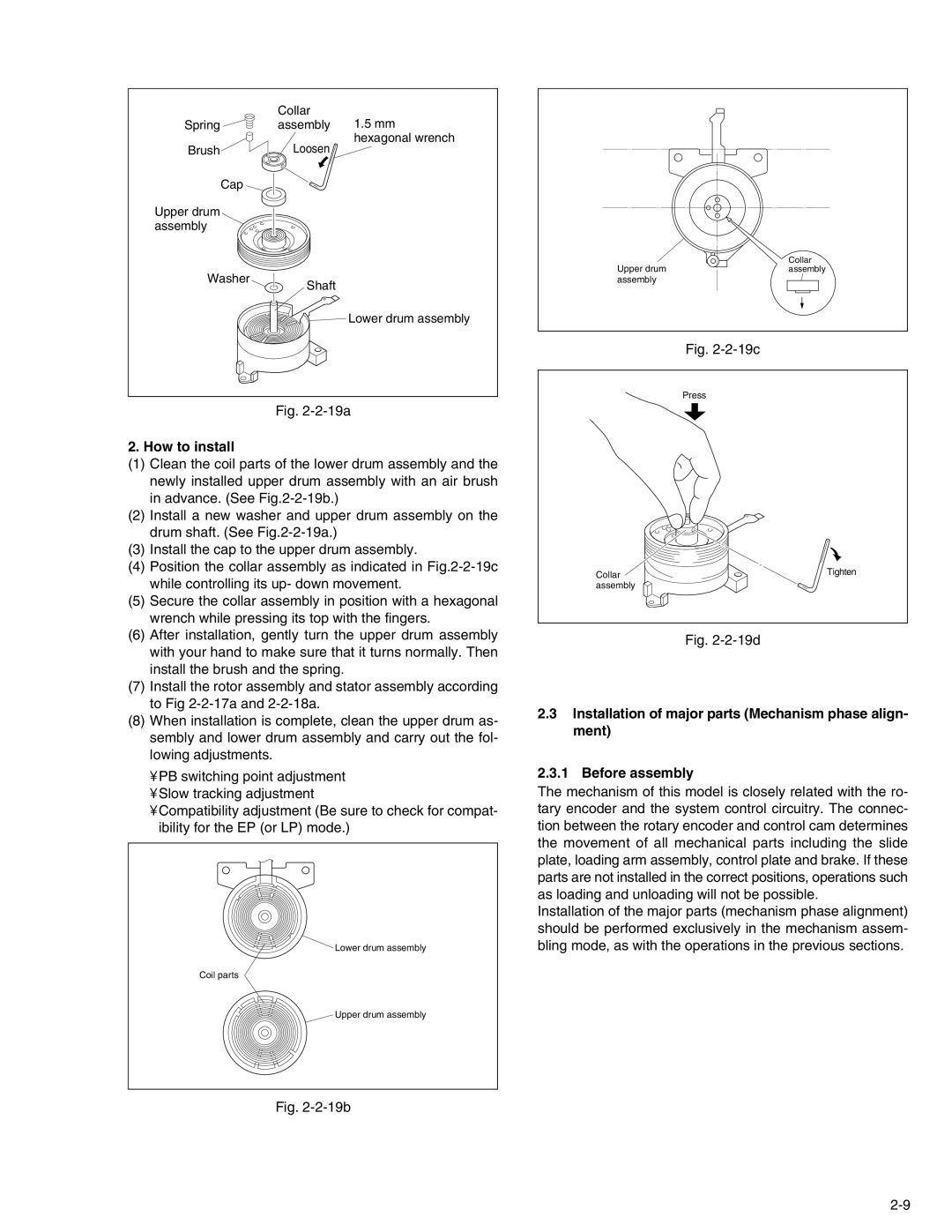
Collar
Springassembly 1.5 mm
hexagonal wrench
BrushLoosen
Cap
Upper drum assembly
Washer
Shaft
![]()
![]() Lower drum assembly
Lower drum assembly
Fig. 2-2-19a
2. How to install
(1)Clean the coil parts of the lower drum assembly and the newly installed upper drum assembly with an air brush in advance. (See
(2)Install a new washer and upper drum assembly on the drum shaft. (See
(3)Install the cap to the upper drum assembly.
(4)Position the collar assembly as indicated in
(5)Secure the collar assembly in position with a hexagonal wrench while pressing its top with the fingers.
(6)After installation, gently turn the upper drum assembly with your hand to make sure that it turns normally. Then install the brush and the spring.
(7)Install the rotor assembly and stator assembly according to Fig
(8)When installation is complete, clean the upper drum as- sembly and lower drum assembly and carry out the fol- lowing adjustments.
•PB switching point adjustment
•Slow tracking adjustment
•Compatibility adjustment (Be sure to check for compat- ibility for the EP (or LP) mode.)
Lower drum assembly
Coil parts
Upper drum assembly
Fig. 2-2-19b
Upper drum | Collar |
assembly | |
assembly |
|
Fig. 2-2-19c
Press
Collar | Tighten |
| |
assembly |
|
Fig. 2-2-19d
2.3Installation of major parts (Mechanism phase align- ment)
2.3.1 Before assembly
The mechanism of this model is closely related with the ro- tary encoder and the system control circuitry. The connec- tion between the rotary encoder and control cam determines the movement of all mechanical parts including the slide plate, loading arm assembly, control plate and brake. If these parts are not installed in the correct positions, operations such as loading and unloading will not be possible.
Installation of the major parts (mechanism phase alignment) should be performed exclusively in the mechanism assem- bling mode, as with the operations in the previous sections.