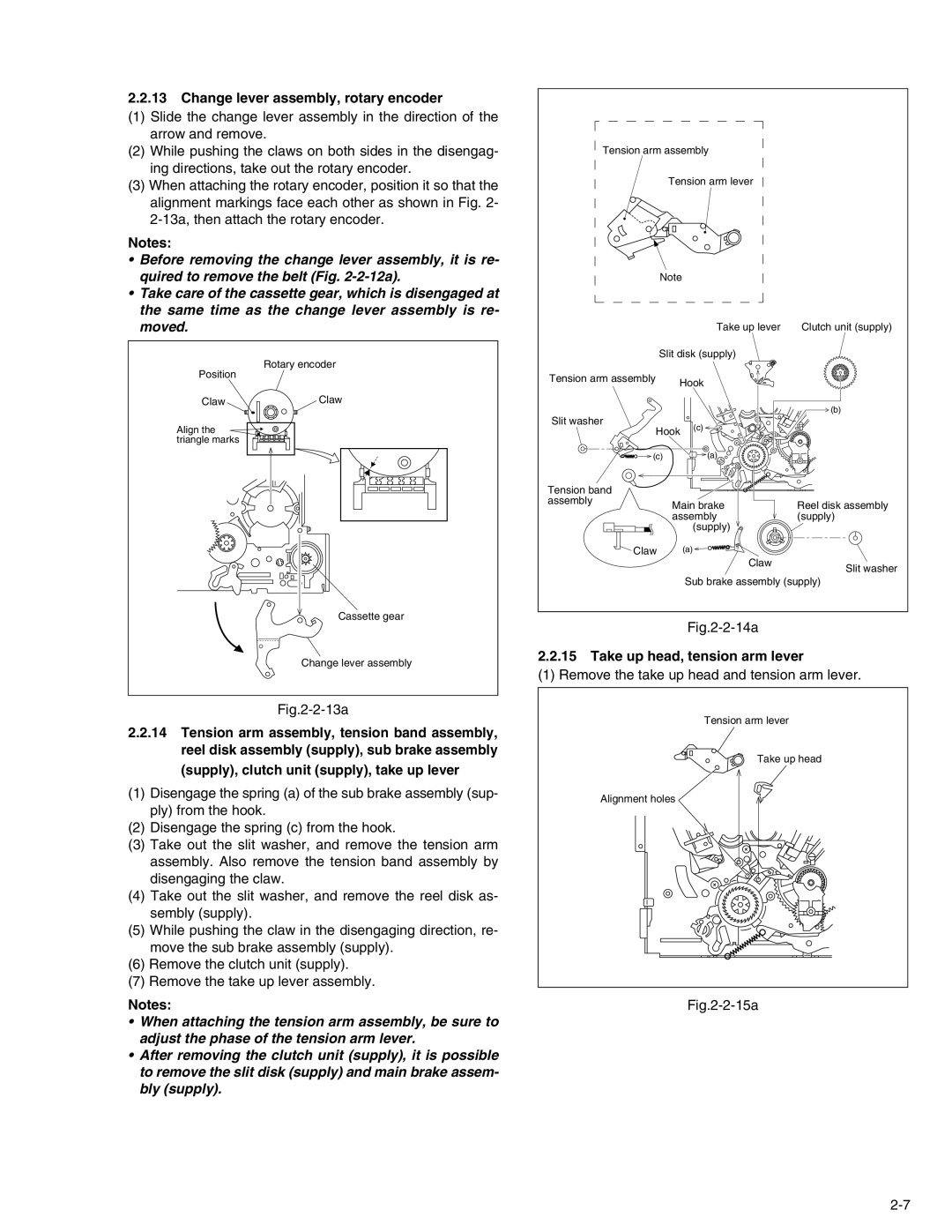
2.2.13Change lever assembly, rotary encoder
(1)Slide the change lever assembly in the direction of the arrow and remove.
(2)While pushing the claws on both sides in the disengag- ing directions, take out the rotary encoder.
(3)When attaching the rotary encoder, position it so that the alignment markings face each other as shown in Fig. 2-
Notes:
•Before removing the change lever assembly, it is re- quired to remove the belt (Fig.
•Take care of the cassette gear, which is disengaged at the same time as the change lever assembly is re- moved.
Position | Rotary encoder |
| |
Claw | Claw |
Align the |
|
triangle marks |
|
Cassette gear
Change lever assembly
Fig.2-2-13a
2.2.14Tension arm assembly, tension band assembly, reel disk assembly (supply), sub brake assembly (supply), clutch unit (supply), take up lever
(1)Disengage the spring (a) of the sub brake assembly (sup- ply) from the hook.
(2)Disengage the spring (c) from the hook.
(3)Take out the slit washer, and remove the tension arm assembly. Also remove the tension band assembly by disengaging the claw.
(4)Take out the slit washer, and remove the reel disk as- sembly (supply).
(5)While pushing the claw in the disengaging direction, re- move the sub brake assembly (supply).
(6)Remove the clutch unit (supply).
(7)Remove the take up lever assembly.
Notes:
•When attaching the tension arm assembly, be sure to adjust the phase of the tension arm lever.
•After removing the clutch unit (supply), it is possible to remove the slit disk (supply) and main brake assem- bly (supply).
Tension arm assembly |
| ||
| Tension arm lever |
| |
Note |
|
| |
|
| Take up lever | Clutch unit (supply) |
Slit disk (supply) |
| ||
Tension arm assembly | Hook |
| |
|
| ||
|
|
| (b) |
Slit washer |
| (c) |
|
Hook |
| ||
|
| ||
(c) |
| (a) |
|
Tension band |
|
|
|
assembly | Main brake | Reel disk assembly | |
| |||
| assembly | (supply) | |
|
| (supply) |
|
Claw |
| (a) |
|
|
| Claw | Slit washer |
|
|
| |
|
| Sub brake assembly (supply) | |
|
|
|
|
2.2.15 Take up head, tension arm lever
(1) Remove the take up head and tension arm lever.
Tension arm lever
Take up head
Alignment holes
