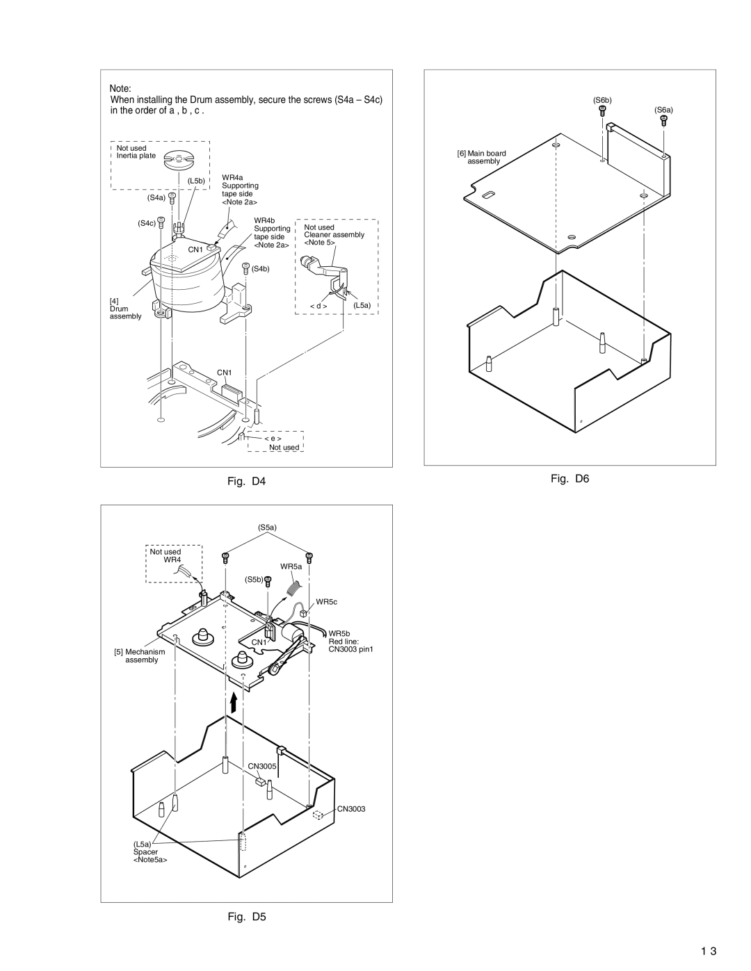
Note:
When installing the Drum assembly, secure the screws (S4a – S4c) in the order of a , b , c .
(S6b)
(S6a)
Not used
Inertia plate
(L5b)
(S4a) ![]()
![]()
![]()
(S4c) ![]()
CN1 ![]()
[4] Drum assembly
WR4a Supporting tape side <Note 2a>
WR4b | Not used |
|
Supporting |
| |
tape side | Cleaner assembly | |
<Note 2a> | <Note 5> |
|
|
| |
(S4b) |
|
|
| < d > | (L5a) |
CN1
< e > Not used
[6]Main board assembly
Fig. D4
Fig. D6
Not used
WR4
[5]Mechanism assembly
(L5a) Spacer <Note5a>
(S5a)
WR5a
(S5b)![]()
WR5c
| WR5b |
CN1 | Red line: |
| CN3003 pin1 |
CN3005
CN3003