2.5Compatibility adjustment Notes:
• Although compatibility adjustment is very important, it is not necessary to perform this as part of the nor- mal servicing work. It will be required when you have replaced the audio control head, drum assembly or any part of the tape transport system.
• To avoid any damage to the alignment tape while per- forming the compatibility adjustment, get a separate cassette tape (for recording and play back) ready to be used for checking the initial tape running behavior.
• Unless otherwise specified, all measuring points and adjustment parts are located on the Main board.
• When using the Jig RCU, set its custom code to match the custom code of the VCR.
(7)Make sure that the V.PB FM waveform varies in parallel and linearly with the tracking operation again. When re- quired, perform
(8)Unload the cassette tape once, play back the alignment tape (A1) again and confirm the V.PB FM waveform.
(9)After adjustment, confirm that the tape wrinkling does not occur at the roller upper or lower limits. (See Fig.
(10)After completing adjustment, tighten the set screw at the bottom of the pole base assembly. (Be careful not to tighten it too much.) (See Fig.
[Perform adjustment step (11) only for the models equipped with SP mode and EP (or LP) mode.]
(11) Repeat steps (1) to (10) by using the alignment tape (A2).
Jig RCU
[Data transmitting method] Depress the “ ![]() ” ( 3 ) button after the data code is set.
” ( 3 ) button after the data code is set.
CUSTOM CODE
43: A | CODE |
|
|
|
|
53: B | CODE |
|
|
|
|
DATA CODE
INITIAL MODE
Fig. 2-5a Jig RCU [PTU94023B]
2.5.1 FM waveform linearity
|
|
| |
Signal | (A1) | • Alignment tape(SP, stairstep, PAL) [MHPE] |
|
| (A2) | • Alignment tape(LP, stairstep, PAL) |
|
|
| - - - - - - - - - - - - - - - - - - - - - - - - - - - - - - - - - - - - - - - - - |
|
|
|
| |
| (A1) | • Alignment tape(SP, stairstep, NTSC) [MHP] |
|
| (A2) | • Alignment tape(EP, stairstep, NTSC) |
|
Mode | (B) | • PB |
|
|
|
|
|
Equipment | (C) | • Oscilloscope |
|
|
|
|
|
Measuring point | (D) | • TP106 (PB FM) |
|
|
|
|
|
External trigger | (E) | • TP111 (D.FF) |
|
|
|
|
|
Adjustment part | (F) | • Guide roller [Mechanism assembly] |
|
|
|
|
|
Specified value | (G) | • Flat V.PB FM waveform |
|
|
|
|
|
Adjustment tool | (H) | • Hexagonal wrench (1.25 mm) |
|
|
| • Roller driver [PTU94002] |
|
(1)Play back the alignment tape (A1).
(2)Apply the external trigger signal to D.FF (E), to observe the V.PB FM waveform at the measuring point (D).
(3)Set the VCR to the manual tracking mode.
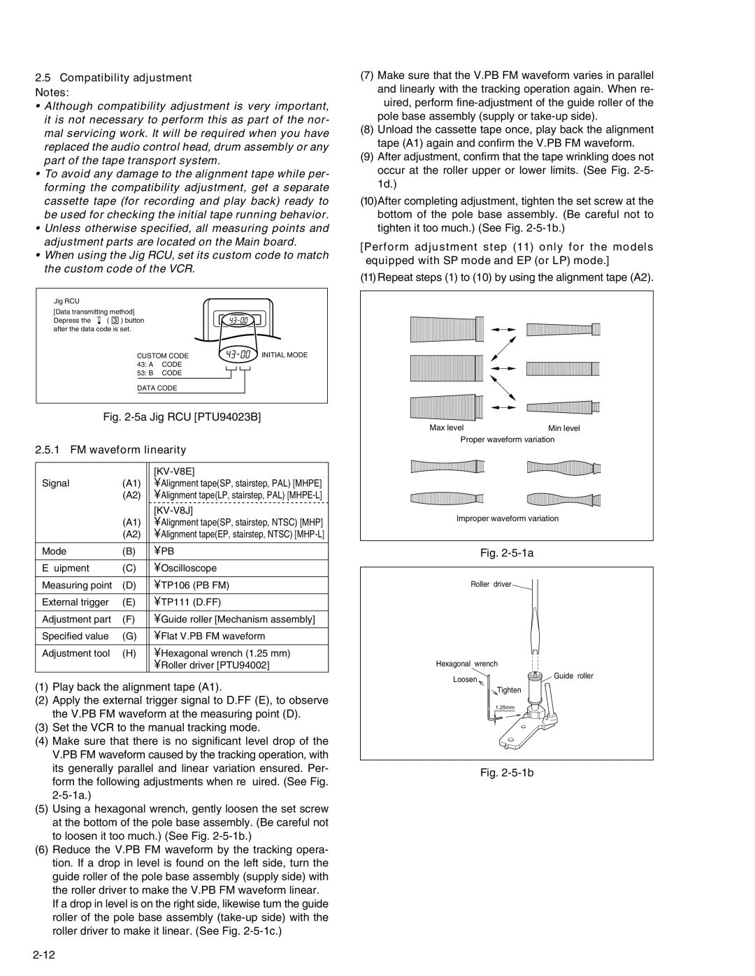
(4)Make sure that there is no significant level drop of the V.PB FM waveform caused by the tracking operation, with its generally parallel and linear variation ensured. Per- form the following adjustments when required. (See Fig.
(5)Using a hexagonal wrench, gently loosen the set screw at the bottom of the pole base assembly. (Be careful not to loosen it too much.) (See Fig.
(6)Reduce the V.PB FM waveform by the tracking opera- tion. If a drop in level is found on the left side, turn the guide roller of the pole base assembly (supply side) with the roller driver to make the V.PB FM waveform linear.
If a drop in level is on the right side, likewise turn the guide roller of the pole base assembly
Max levelMin level Proper waveform variation
Improper waveform variation
Fig. 2-5-1a
Roller driver
Hexagonal wrench
Loosen | Guide roller |
| |
| Tighten |
| 1.25mm |