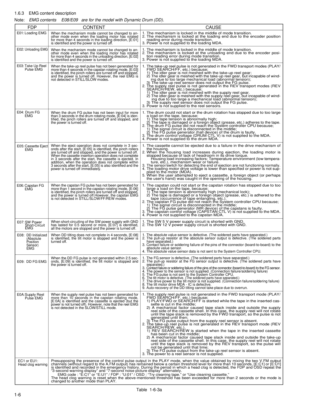
1.6.3EMG content description
Note: EMG contents “E08/E09” are for the model with Dynamic Drum (DD).
FDP | CONTENT |
| CAUSE |
E01: Loading EMG | When the mechanism mode cannot be changed to an- | 1. | The mechanism is locked in the middle of mode transition. |
| other mode even when the loading motor has rotated | 2. The mechanism is locked at the loading end due to the encoder position | |
| for more than 4 seconds in the loading direction, [E:01] |
| reading error during mode transition. |
| is identified and the power is turned off. | 3. | Power is not supplied to the loading MDA. |
|
|
|
|
E02: Unloading EMG | When the mechanism mode cannot be changed to an- | 1. | The mechanism is locked in the middle of mode transition. |
| other mode even when the loading motor has rotated | 2. | The mechanism is locked at the unloading end due to the encoder posi- |
| for more than 4 seconds in the unloading direction, [E:02] |
| tion reading error during mode transition. |
| is identified and the power is turned off. | 3. | Power is not supplied to the loading MDA. |
|
|
|
|
E03: Take Up Reel | When the | 1. | The |
Pulse EMG | more than 4 seconds in the capstan rotating mode, [E:03] |
| FWD SEARCH/FF, etc.) because; |
| is identified, the pinch rollers are turned off and stopped, |
| 1) The idler gear is not meshed with the |
| and the power is turned off. However, the reel EMG is |
| 2) The idler gear is meshed with the |
| not detected in STILL/SLOW modes. |
| ing due to too large mechanical load (abnormal tension); |
|
|
| 3) The |
|
| 2. | The supply reel pulse is not generated in the REV transport modes (REV |
|
|
| SEARCH/REW, etc.) because; |
|
|
| 1) The idler gear is not meshed with the supply reel gear. |
|
|
| 2) The idler gear is meshed with the supply reel gear, but incapable of wind- |
|
|
| ing due to too large a mechanical load (abnormal tension); |
|
|
| 3) The supply reel sensor does not output the FG pulse. |
|
| 3. | Power is not supplied to the reel sensors. |
|
|
|
|
E04: Drum FG | When the drum FG pulse has not been input for more | 1. | The drum could not start or the drum rotation has stopped due to too large |
EMG | than 3 seconds in the drum rotating mode, [E:04] is iden- |
| a load on the tape, because; |
| tified, the pinch rollers are turned off and stopped, and |
| 1) The tape tension is abnormally high; |
| the power is turned off. | 2. | 2) The tape is damaged or a foreign object (grease, etc.) adheres to the tape. |
|
| The drum FG pulse did not reach the System controller CPU because; | |
|
|
| 1) The signal circuit is disconnected in the middle; |
|
|
| 2) The FG pulse generator (hall device) of the drum is faulty. |
|
| 3. | The drum control voltage (DRUM CTL V) is not supplied to the MDA. |
|
| 4. | Power is not supplied to the drum MDA. |
|
|
|
|
E05: Cassette Eject | When the eject operation does not complete in 3 sec- | 1. | The cassette cannot be ejected due to a failure in the drive mechanism of |
EMG | onds after the start, [E:05] is identified, the pinch rollers |
| the housing. |
| are turned off and stopped, and the power is turned off. | 2. When the housing load increases during ejection, the loading motor is | |
| When the cassette insertion operation does not complete |
| stopped because of lack of headroom in its drive torque. |
| in 3 seconds after the start, the cassette is ejected. In |
| Housing load increasing factors: Temperature environment (low tempera- |
| addition, when the operation does not complete within |
| ture, etc.), mechanism wear or failure. |
| 3 seconds after the start, [E:05] is also identified and the | 3. | The sensor/switch for detecting the end of ejection are not functioning normally. |
| power is turned off immediately. | 4. | The loading motor drive voltage is lower than specified or power is not sup- |
|
|
| plied to the motor (MDA). |
|
| 5. | When the user attempted to eject a cassette, a foreign object (or perhaps |
|
|
| the user's hand) was caught in the opening of the housing. |
|
|
|
|
E06: Capstan FG | When the capstan FG pulse has not been generated for | 1. | The capstan could not start or the capstan rotation has stopped due to too |
EMG | more than 1 second in the capstan rotating mode, [E:06] |
| large a load on the tape, because; |
| is identified, the pinch rollers are turned off and stopped, |
| 1) The tape tension is abnormally high (mechanical lock); |
| and the power is turned off.However, the capstan EMG |
| 2) The tape is damaged or a foreign object (grease, etc.) is adhered to the |
| is not detected in STILL/SLOW/FF/REW modes. | 2. | tape (occurrence of tape entangling, etc.). |
|
| The capstan FG pulse did not reach the System controller CPU because; | |
|
|
| 1) The signal circuit is disconnected in the middle; |
|
|
| 2) The FG pulse generator (MR device) of the capstans is faulty. |
|
| 3. | The capstan control voltage (CAPSTAN CTL V) is not supplied to the MDA. |
|
| 4. | Power is not supplied to the capstan MDA. |
|
|
|
|
E07: SW Power | When | 1. | The SW 5 V power supply circuit is shorted with GND. |
has lasted for 0.5 second or more, [E:07] is identified, | 2. | The SW 12 V power supply circuit is shorted with GND. | |
EMG | all the motors are stopped and the power is turned off. |
|
|
|
|
|
|
E08: DD Initialized | When DD tilting does not complete in 4 seconds, [E:08] | 1. | The absolute value sensor is defective. (The soldered parts have separated.) |
(Absolute | is identified, the tilt motor is stopped and the power is | 2. | The |
Position | turned off. |
| have separated.) |
Sensor) |
| 3. | Contact failure or soldering failure of the pins of the connector |
EMG |
| 4. | absolute value sensor. |
|
| The absolute value sensor data is not sent to the System Controller CPU. | |
|
|
| |
| When the DD FG pulse is not generated within 2.5 sec- | 1. The FG sensor is defective. (The soldered parts have separated.) | |
E09: DD FG EMG | onds, [E:09] is identified, the tilt motor is stopped and | 2. | The |
| the power is turned off. | 3. | separated.) |
|
| Contact failure or soldering failure of the pins of the connector | |
|
| 4. | The power to the sensor is not supplied. (Connection failure/soldering failure) |
|
| 5. | The FG pulse is not sent to the System Controller CPU. |
|
| 6. | The tilt motor is defective. (The soldered parts have separated.) |
|
| 7. | The drive power to the tilt motor is not supplied. (Connection failure/soldering failure) |
|
| 8. | The tilt motor drive MDA - IC is defective. |
|
| 9. | |
|
|
|
|
E0A:Supply Reel | When the supply reel pulse has not been generated for | 1. | The supply reel pulse is not generated in the FWD transport mode (PLAY/ |
Pulse EMG | more than 10 seconds in the capstan rotating mode, |
| FWD SEARCH/FF, etc.) because; |
| [E:0A] is identified and the cassette is ejected (but the |
| 1) PLAY/FWD or SEARCH/FF is started while the tape in the inserted cas- |
| power is not turned off). However, note that the reel EMG |
| sette is cut in the middle; |
| is not detected in the SLOW/STILL mode. |
| 2) A mechanical factor caused tape slack inside and outside the supply |
|
|
| reel side of the cassette shell. In this case, the supply reel will not rotate |
|
|
| until the tape slack is removed by the FWD transport, so the pulse is not |
|
|
| generated until then; |
|
|
| 3) The FG pulse output from the supply reel sensor is absent. |
|
| 2. | The |
|
|
| SEARCH/REW, etc.). |
|
|
| 1) REV SEARCH/REW is started when the tape in the inserted cassette |
|
|
| has been cut in the middle; |
|
|
| 2) A mechanical factor caused tape slack inside and outside the |
|
|
| reel side of the cassette shell. In this case, the supply reel will not rotate |
|
|
| until the tape slack is removed by the REV transport, so the pulse will |
|
|
| not be generated until that time; |
|
|
| 3) The FG pulse output from the |
|
| 3. | The power to a reel sensor is not supplied. |
|
|
| |
EC1 or EU1: | Presupposing the presence of the control pulse output in the PLAY mode, when the value obtained by mixing the two V.FM output | ||
Head clog warning | channels (without regard to the A.FM output) has remained below a certain threshold level for more than 10 seconds, [E:C1] or [E:U1] | ||
| is identified and recorded in the emergency history. During the period in which a head clog is detected, the FDP and OSD repeat the | ||
| |||
| EMG code : “E:C1” or “E:U1” / FDP : “U:01” / OSD : “Try cleaning tape.” or “Use cleaning cassette.” | ||
| The head clog warning is reset when the | ||
| changed to another mode than PLAY. |
|
|
|
|
|
|
Table