2.3.2 Loading arm assemblies (supply, take up)
(1)Attach the loading arm assembly (supply) and loading arm assembly (take up) so that the alignment markings on their gears face each other and the holes on their arms are respectively aligned with the holes on the main deck.
(2)Attach the guide rail, attach the pole base assemblies onto the extremities of the arms, then perform the unloading operation so that the pole base assemblies come to the most forward positions.
Note:
•When attaching the pole base assemblies (supply/take up), temporarily tighten the 3 screws other than the 2 screws on the sides of the guide rail extremities so that the parts do not slip out.
(3) Attach the surrounding parts of the guide rail.
Loading arm assembly (supply)
To pole base | To pole base assembly | |
assembly |
|
|
| Correct direction | Loading arm |
| assembly | |
|
| |
|
| (take up) |
|
| Holes align with |
Holes align with |
| hole in deck |
|
| |
hole in deck |
|
|
Correct direction |
Fig. 2-3-2a
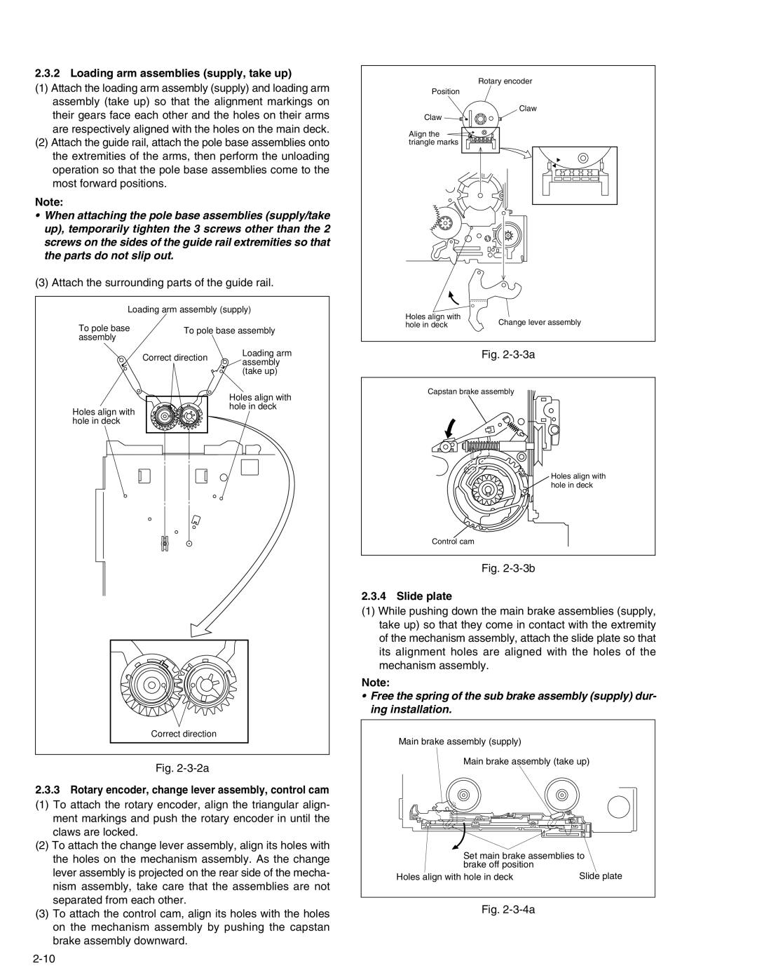
2.3.3Rotary encoder, change lever assembly, control cam
(1) To attach the rotary encoder, align the triangular align- ment markings and push the rotary encoder in until the claws are locked.
(2) To attach the change lever assembly, align its holes with the holes on the mechanism assembly. As the change lever assembly is projected on the rear side of the mecha- nism assembly, take care that the assemblies are not separated from each other.
(3) To attach the control cam, align its holes with the holes on the mechanism assembly by pushing the capstan brake assembly downward.
Rotary encoder
Position
Claw
Claw
Align the triangle marks
Holes align with | Change lever assembly | |
hole in deck | ||
|
Fig. 2-3-3a
Capstan brake assembly
Holes align with hole in deck
Control cam
Fig. 2-3-3b
2.3.4 Slide plate
(1)While pushing down the main brake assemblies (supply, take up) so that they come in contact with the extremity of the mechanism assembly, attach the slide plate so that its alignment holes are aligned with the holes of the mechanism assembly.
Note:
•Free the spring of the sub brake assembly (supply) dur- ing installation.
Main brake assembly (supply)
Main brake assembly (take up)
Set main brake assemblies to brake off position
Holes align with hole in deck | Slide plate |