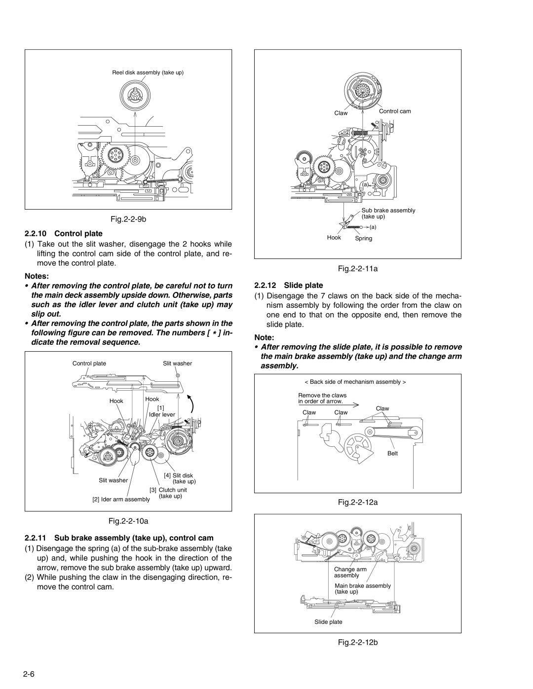
Reel disk assembly (take up)
Fig.2-2-9b
2.2.10Control plate
(1)Take out the slit washer, disengage the 2 hooks while lifting the control cam side of the control plate, and re- move the control plate.
Notes:
•After removing the control plate, be careful not to turn the main deck assembly upside down. Otherwise, parts such as the idler lever and clutch unit (take up) may slip out.
•After removing the control plate, the parts shown in the
following figure can be removed. The numbers [ * ] in- dicate the removal sequence.
Control plate | Slit washer |
Claw | Control cam |
|
(a)![]()
Sub brake assembly (take up)
![]()
![]() (a)
(a)
Hook Spring
Fig.2-2-11a
2.2.12Slide plate
(1)Disengage the 7 claws on the back side of the mecha- nism assembly by following the order from the claw on one end to that on the opposite end, then remove the slide plate.
Note:
•After removing the slide plate, it is possible to remove the main brake assembly (take up) and the change arm assembly.
< Back side of mechanism assembly >
Hook | Hook |
| |
| [1] |
| Idler lever |
Slit washer | [4] Slit disk |
(take up) |
[3] Clutch unit
Remove the claws in order of arrow.
Claw Claw
Claw
Belt
[2] Ider arm assembly
Fig.2-2-10a
(take up)
Fig.2-2-12a
2.2.11Sub brake assembly (take up), control cam
(1)Disengage the spring (a) of the
(2)While pushing the claw in the disengaging direction, re- move the control cam.
Change arm assembly
Main brake assembly (take up)
Slide plate