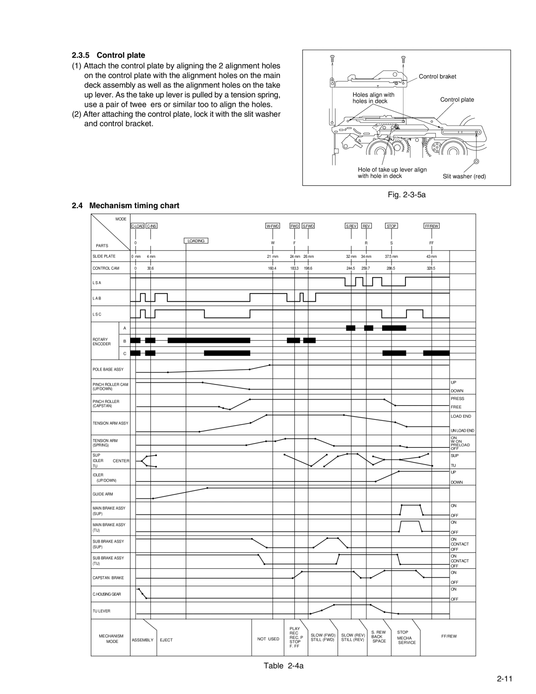
2.3.5 Control plate
(1)Attach the control plate by aligning the 2 alignment holes on the control plate with the alignment holes on the main deck assembly as well as the alignment holes on the take up lever. As the take up lever is pulled by a tension spring, use a pair of tweezers or similar too to align the holes.
(2)After attaching the control plate, lock it with the slit washer and control bracket.
| Control braket |
Holes align with | Control plate |
holes in deck |
Hole of take up lever align |
|
with hole in deck | Slit washer (red) |
Fig. 2-3-5a
2.4 Mechanism timing chart
| MODE |
|
|
|
|
|
|
|
|
|
|
|
|
|
|
|
|
| FWD | S.FWD | S.REV | REV | STOP |
| FF/REW | ||||
|
| 0 |
|
| LOADING | W | F |
|
|
| R | S |
| FF |
PARTS |
|
|
|
|
|
|
|
| ||||||
|
|
|
|
|
|
|
|
|
|
|
|
|
| |
SLIDE PLATE | 0 mm | 4 mm |
|
| 21 mm | 24 mm | 26 mm | 32 mm | 34 mm | 37.5 mm | 43 mm | |||
CONTROL CAM | 0° | 30.6° |
|
| 160.4° | 183.3° |
| 198.6° | 244.5° | 259.7° | 286.5° |
| 328.5° | |
L S A |
|
|
|
|
|
|
|
|
|
|
|
|
|
|
L A B |
|
|
|
|
|
|
|
|
|
|
|
|
|
|
L S C |
|
|
|
|
|
|
|
|
|
|
|
|
|
|
| A |
|
|
|
|
|
|
|
|
|
|
|
|
|
ROTARY | B |
|
|
|
|
|
|
|
|
|
|
|
|
|
ENCODER |
|
|
|
|
|
|
|
|
|
|
|
|
| |
|
|
|
|
|
|
|
|
|
|
|
|
|
| |
| C |
|
|
|
|
|
|
|
|
|
|
|
|
|
POLE BASE ASSY |
|
|
|
|
|
|
|
|
|
|
|
|
| |
PINCH ROLLER CAM |
|
|
|
|
|
|
|
|
|
|
|
| UP | |
|
|
|
|
|
|
|
|
|
|
|
|
| ||
(UP/DOWN) |
|
|
|
|
|
|
|
|
|
|
|
|
| DOWN |
|
|
|
|
|
|
|
|
|
|
|
|
|
| |
PINCH ROLLER |
|
|
|
|
|
|
|
|
|
|
|
| PRESS | |
|
|
|
|
|
|
|
|
|
|
|
|
| ||
(CAPSTAN) |
|
|
|
|
|
|
|
|
|
|
|
|
| FREE |
|
|
|
|
|
|
|
|
|
|
|
|
|
| LOAD END |
TENSION ARM ASSY |
|
|
|
|
|
|
|
|
|
|
|
|
| |
|
|
|
|
|
|
|
|
|
|
|
|
|
| UN LOAD END |
TENSION ARM |
|
|
|
|
|
|
|
|
|
|
|
| ON | |
|
|
|
|
|
|
|
|
|
|
|
| W ON | ||
(SPRING) |
|
|
|
|
|
|
|
|
|
|
|
|
| PRELOAD |
|
|
|
|
|
|
|
|
|
|
|
|
|
| OFF |
SUP |
|
|
|
|
|
|
|
|
|
|
|
|
| SUP |
IDLER | CENTER |
|
|
|
|
|
|
|
|
|
|
|
|
|
TU |
|
|
|
|
|
|
|
|
|
|
|
|
| TU |
IDLER |
|
|
|
|
|
|
|
|
|
|
|
|
| UP |
|
|
|
|
|
|
|
|
|
|
|
|
|
| |
(UP/DOWN) |
|
|
|
|
|
|
|
|
|
|
|
| DOWN | |
|
|
|
|
|
|
|
|
|
|
|
|
|
| |
GUIDE ARM |
|
|
|
|
|
|
|
|
|
|
|
|
|
|
MAIN BRAKE ASSY |
|
|
|
|
|
|
|
|
|
|
|
| ON | |
|
|
|
|
|
|
|
|
|
|
|
|
| ||
(SUP) |
|
|
|
|
|
|
|
|
|
|
|
|
| OFF |
|
|
|
|
|
|
|
|
|
|
|
|
|
| |
MAIN BRAKE ASSY |
|
|
|
|
|
|
|
|
|
|
|
| ON | |
|
|
|
|
|
|
|
|
|
|
|
|
| ||
(TU) |
|
|
|
|
|
|
|
|
|
|
|
|
| OFF |
|
|
|
|
|
|
|
|
|
|
|
|
|
| |
SUB BRAKE ASSY |
|
|
|
|
|
|
|
|
|
|
|
| ON | |
|
|
|
|
|
|
|
|
|
|
|
| CONTACT | ||
(SUP) |
|
|
|
|
|
|
|
|
|
|
|
|
| |
|
|
|
|
|
|
|
|
|
|
|
|
| OFF | |
|
|
|
|
|
|
|
|
|
|
|
|
|
| |
SUB BRAKE ASSY |
|
|
|
|
|
|
|
|
|
|
|
| ON | |
|
|
|
|
|
|
|
|
|
|
|
| CONTACT | ||
(TU) |
|
|
|
|
|
|
|
|
|
|
|
|
| |
|
|
|
|
|
|
|
|
|
|
|
|
| OFF | |
|
|
|
|
|
|
|
|
|
|
|
|
|
| |
|
|
|
|
|
|
|
|
|
|
|
|
|
| ON |
CAPSTAN BRAKE |
|
|
|
|
|
|
|
|
|
|
|
|
| |
|
|
|
|
|
|
|
|
|
|
|
|
|
| OFF |
|
|
|
|
|
|
|
|
|
|
|
|
|
| ON |
C.HOUSING GEAR |
|
|
|
|
|
|
|
|
|
|
|
|
| |
|
|
|
|
|
|
|
|
|
|
|
|
|
| OFF |
TU LEVER |
|
|
|
|
|
|
|
|
|
|
|
|
|
|
|
|
|
|
|
|
| PLAY |
|
|
|
| S. REW | STOP |
|
MECHANISM |
|
|
|
|
| REC |
| SLOW (FWD) | SLOW (REV) | FF/REW | ||||
|
|
|
| NOT USED | REC. P | BACK | MECHA | |||||||
MODE | ASSEMBLY | EJECT |
| STILL (FWD) | STILL (REV) | SPACE |
| |||||||
| STOP |
| SERVICE |
| ||||||||||
|
|
|
|
|
|
|
|
|
| |||||
|
|
|
|
|
|
| F. FF |
|
|
|
|
|
|
|
|
|
|
|
|
| Table |
|
|
|
|
|
| ||