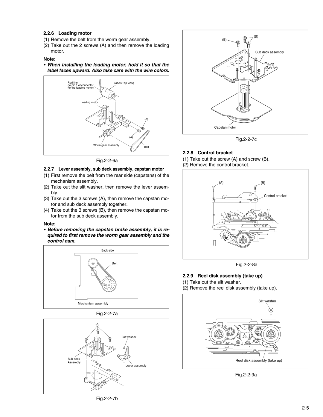
2.2.6 Loading motor
(1)Remove the belt from the worm gear assembly.
(2)Take out the 2 screws (A) and then remove the loading motor.
Note:
•When installing the loading motor, hold it so that the label faces upward. Also take care with the wire colors.
(B)
(B)
Sub deck assembly
Red line
(to pin 1 of connector for the loading motor)
Loading motor
Label (Top view)
(A)
(A)
Capstan motor
Fig.2-2-7c
Worm gear assembly
Fig.2-2-6a
Belt
2.2.8 Control bracket
(1)Take out the screw (A) and screw (B).
(2)Remove the control bracket.
2.2.7Lever assembly, sub deck assembly, capstan motor
(1) First remove the belt from the rear side (capstans) of the mechanism assembly.
(2) Take out the slit washer, then remove the lever assem- bly.
(3) Take out the 3 screws (A), then remove the capstan mo- tor and sub deck assembly together.
(4) Take out the 3 screws (B), then remove the capstan mo- tor from the sub deck assembly.
Note:
•Before removing the capstan brake assembly, it is re- quired to first remove the worm gear assembly and the control cam.
Back side
Belt
Mechanism assembly
Fig.2-2-7a
(A)
Slit washer
Sub deck
Assembly
Lever assembly
Fig.2-2-7b
(A)(B)
Control bracket
Fig.2-2-8a
2.2.9Reel disk assembly (take up)
(1) Take out the slit washer.
(2) Remove the reel disk assembly (take up).
Slit washer
Reel disk assembly (take up)