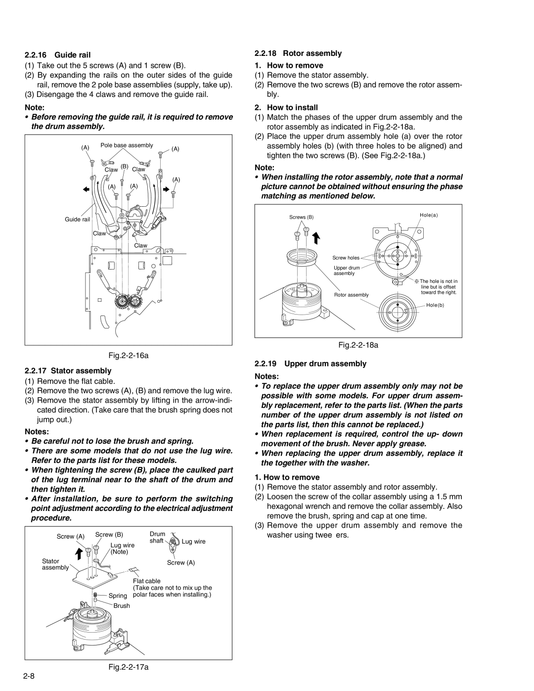
2.2.16Guide rail
(1)Take out the 5 screws (A) and 1 screw (B).
(2)By expanding the rails on the outer sides of the guide rail, remove the 2 pole base assemblies (supply, take up).
(3)Disengage the 4 claws and remove the guide rail.
Note:
• Before removing the guide rail, it is required to remove the drum assembly.
(A) | Pole base assembly | (A) |
|
Claw (B) Claw
(A)
(A) (A)
2.2.18 Rotor assembly
1. How to remove
(1)Remove the stator assembly.
(2)Remove the two screws (B) and remove the rotor assem- bly.
2. How to install
(1)Match the phases of the upper drum assembly and the rotor assembly as indicated in
(2)Place the upper drum assembly hole (a) over the rotor assembly holes (b) (with three holes to be aligned) and tighten the two screws (B). (See
Note:
•When installing the rotor assembly, note that a normal picture cannot be obtained without ensuring the phase matching as mentioned below.
Guide rail
Claw
Claw
Screws (B)
Screw holes
Upper drum assembly
Rotor assembly
Hole(a)
![]()
![]()
![]() The hole is not in line but is offset toward the right.
The hole is not in line but is offset toward the right.
Hole(b)
Fig.2-2-16a
2.2.17Stator assembly
(1) Remove the flat cable.
(2) Remove the two screws (A), (B) and remove the lug wire.
(3) Remove the stator assembly by lifting in the
Notes:
•Be careful not to lose the brush and spring.
•There are some models that do not use the lug wire. Refer to the parts list for these models.
•When tightening the screw (B), place the caulked part of the lug terminal near to the shaft of the drum and then tighten it.
•After installation, be sure to perform the switching point adjustment according to the electrical adjustment procedure.
Screw (A) | Screw (B) | Drum |
|
| shaft | Lug wire | |
|
| ||
| Lug wire |
| |
| (Note) |
|
|
Stator |
|
| Screw (A) |
assembly |
|
|
|
|
| Flat cable |
|
|
| (Take care not to mix up the | |
| Spring | polar faces when installing.) | |
Brush
Fig.2-2-18a
2.2.19 Upper drum assembly
Notes:
•To replace the upper drum assembly only may not be possible with some models. For upper drum assem- bly replacement, refer to the parts list. (When the parts number of the upper drum assembly is not listed on the parts list, then this cannot be replaced.)
•When replacement is required, control the up- down movement of the brush. Never apply grease.
•When replacing the upper drum assembly, replace it the together with the washer.
1. How to remove
(1)Remove the stator assembly and rotor assembly.
(2)Loosen the screw of the collar assembly using a 1.5 mm hexagonal wrench and remove the collar assembly. Also remove the brush, spring and cap at one time.
(3)Remove the upper drum assembly and remove the washer using tweezers.