SECTION 2
MECHANISM ADJUSTMENT
2.1 Before starting repair and adjustment
2.1.1 Precautions
(1)Unplug the power cord plug of the VCR before using your soldering iron.
(2)Take care not to cause any damage to the conductor wires when plugging and unplugging the connectors.
(3)Do not randomly handle the parts without identifying where the trouble is.
(4)Exercise enough care not to damage the lugs, etc. dur- ing the repair work.
(5)Install the cassette housing assembly only when the mechanism is in the “Mechanism assembling mode” po- sition. (See 2.2.2.)
(6)When reattaching the front panel assembly, make sure that the door opener of the cassette housing assembly is lowered in position prior to the reinstallation. (See SEC-
TION 1 DISASSEMBLY.)
(7)When checking the operation or performing adjustments to the VCP main unit, it is necessary to connect the power cable (Car Cable) to the VCP main unit so that DC power is supplied. Also, when using the remote control unit, it is required to connect the IR receiver. (by using either the provided or optional accessories)
2.1.2 Checking for proper mechanical operations
Enter the mechanism service mode when you want to oper- ate the mechanism when no cassette is loaded. (See 1.5 Mechanism service mode.)
2.1.3 Manually removing the cassette tape
If you cannot remove the cassette tape which is loaded be- cause of any electrical failure, manually remove it by taking the following steps.
(1)Unplug the power cord plug from the power outlet.
(2)Refer to the disassembly procedure and perform the dis- assembly of the major parts before removing the Cas- sette housing assembly.
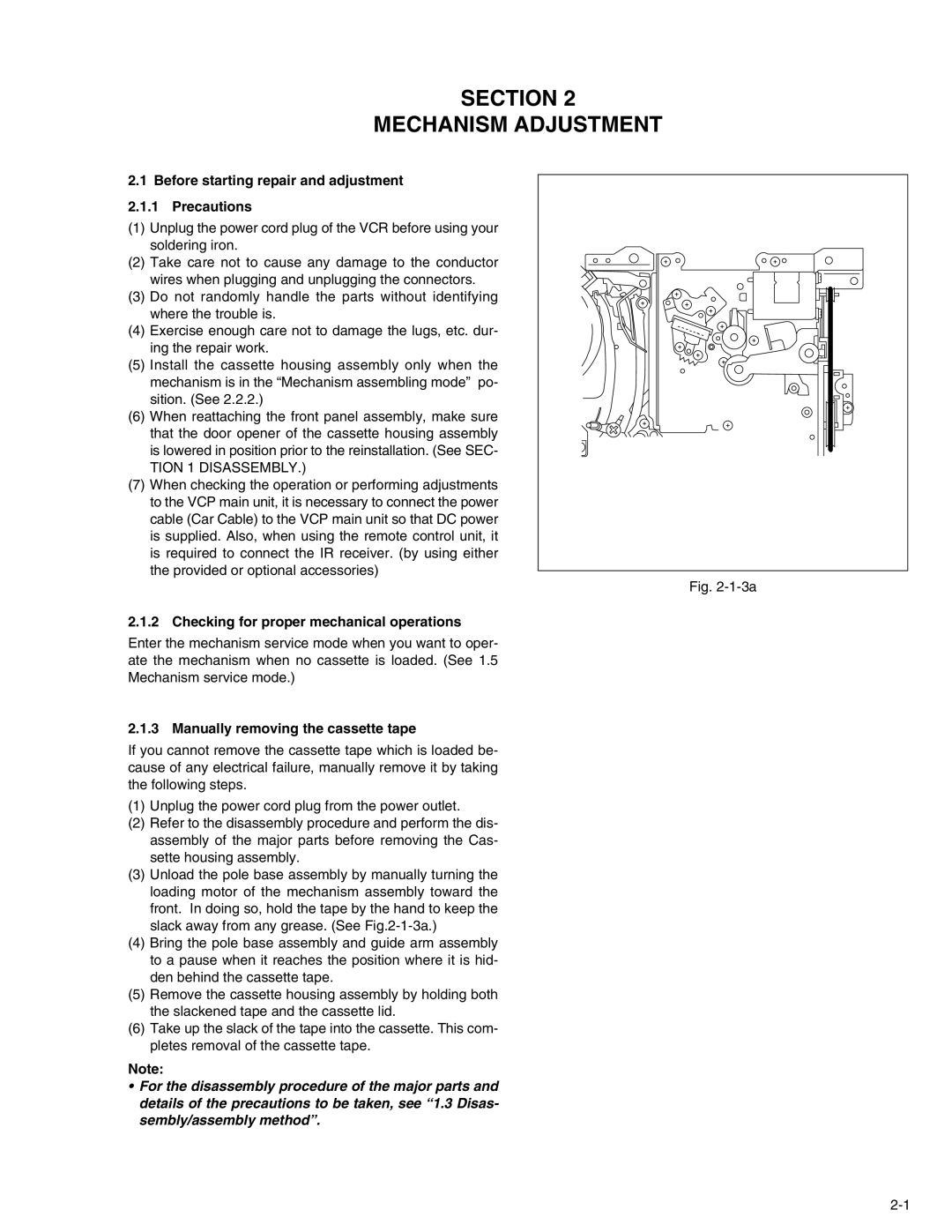
(3)Unload the pole base assembly by manually turning the loading motor of the mechanism assembly toward the front. In doing so, hold the tape by the hand to keep the slack away from any grease. (See
(4)Bring the pole base assembly and guide arm assembly to a pause when it reaches the position where it is hid- den behind the cassette tape.
(5)Remove the cassette housing assembly by holding both the slackened tape and the cassette lid.
(6)Take up the slack of the tape into the cassette. This com- pletes removal of the cassette tape.
Note:
•For the disassembly procedure of the major parts and details of the precautions to be taken, see “1.3 Disas- sembly/assembly method”.
Loading motor |
Guide arm assembly |
Pole base bssembly |
Fig. |
2.1.4 Jigs and tools required for adjustment
Roller driver | A/C head positioning tool | Torque gauge |
PTU94002 | PTU94010 | |
Back tension cassette gauge | Jig RCU | Alignment tape |
PTU94023B | (SP, stairstep, NTSC) | |
|
| MHP |
Alignment tape | Alignment tape | Alignment tape |
(EP, stairstep, NTSC) | (SP, stairstep, PAL) | (LP, stairstep, PAL) |
MHPE |