NOTE: Leave blower access panel installed to maintain power to control center to view current LED status.
4.BRIEFLY remove either wire from the main limit switch until the LED goes out, then reconnect it.
Make sure limit switch wire does not contact any metallic component such as the gas valve. If wire is shorted,
NOTE: If wire to main limit is disconnected longer than 4 sec, the control senses limit circuit is open. Main blower will start and retrieval request will be ignored.
5.When above items have been completed, the component test sequence will occur as described in the Component Test Sequence section above.
NOTE: Be sure to record the status code which is flashed 4 times at start of component test for further troubleshooting.
6.After component test is completed and LED is ON continu- ously indicating the furnace is ready to operate when a signal from the thermostat is received, replace main furnace door.
INITIATING COMPONENT TEST AND RETRIEVING STA- TUS CODE BY JUMPERING CONTROL TEST TERMINAL
1.Remove main furnace door.
2.Remove blower access panel.
3.Manually close blower access panel door switch. Use a piece of tape to hold switch closed.
Blower access panel door switch opens
4.BRIEFLY short (jumper) TEST,
NOTE: If TEST to COM terminals are jumpered longer than 2 sec, LED will flash rapidly, and retrieval request will be ignored.
5.When above items have been completed, the component test sequence will occur as described in the Component Test Sequence section above.
NOTE: Be sure to record the status code which is flashed 4 times at start of component test for further troubleshooting.
6.After component test is completed and furnace is operating properly, release blower access panel door switch, replace blower access panel, and replace main furnace door.
Step 9ÐChecking Heat Tape Operation (If Applicable)
In applications where the ambient temperature around the furnace is 32°F or lower, freeze protection measures are required. If this application is where heat tape has been applied, check to ensure it will operate when low temperatures are present.
NOTE: Heat tape, when used, should be wrapped around the condensate drain trap and drain line. There is no need to use heat tape within the furnace casing. Most heat tapes are temperature
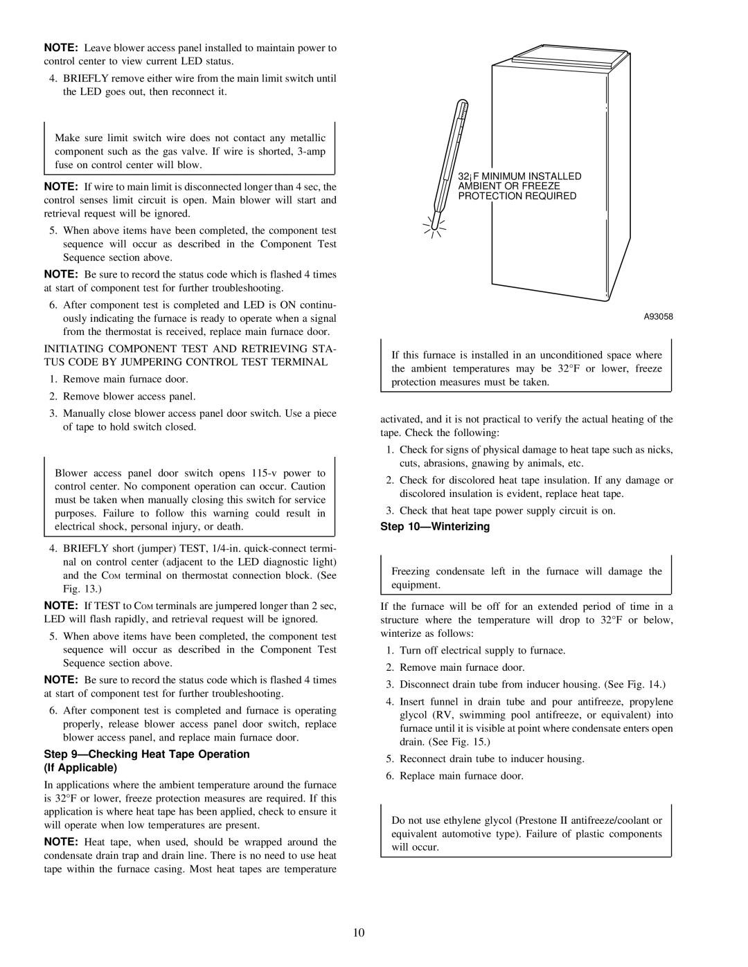
32°F MINIMUM INSTALLED AMBIENT OR FREEZE PROTECTION REQUIRED
A93058
If this furnace is installed in an unconditioned space where the ambient temperatures may be 32°F or lower, freeze protection measures must be taken.
activated, and it is not practical to verify the actual heating of the tape. Check the following:
1.Check for signs of physical damage to heat tape such as nicks, cuts, abrasions, gnawing by animals, etc.
2.Check for discolored heat tape insulation. If any damage or discolored insulation is evident, replace heat tape.
3.Check that heat tape power supply circuit is on.
Step 10ÐWinterizing
Freezing condensate left in the furnace will damage the equipment.
If the furnace will be off for an extended period of time in a structure where the temperature will drop to 32°F or below, winterize as follows:
1.Turn off electrical supply to furnace.
2.Remove main furnace door.
3.Disconnect drain tube from inducer housing. (See Fig. 14.)
4.Insert funnel in drain tube and pour antifreeze, propylene glycol (RV, swimming pool antifreeze, or equivalent) into furnace until it is visible at point where condensate enters open drain. (See Fig. 15.)
5.Reconnect drain tube to inducer housing.
6.Replace main furnace door.
Do not use ethylene glycol (Prestone II antifreeze/coolant or equivalent automotive type). Failure of plastic components will occur.
10