TEST/TWIN
COM W Y R G 24V
HUM ![]()
HUMIDIFIER TERMINAL
LED OPERATION & DIAGNOSTIC LIGHT
| HARNESS CONNECTOR | |
| ||
COOL | ||
BLOWER SPEED | ||
HEAT | ||
| SELECTION TERMINALS | |
| ||
| ||
| ||
| TERMINALS | |
POWER SUPPLY | ||
| ||
| CONNECTION | |
HOT SURFACE | INDUCER MOTOR | |
IGNITOR CONNECTOR | CONNECTOR |
A95086
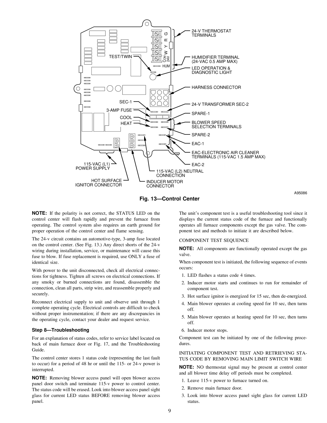
Fig. 13ÐControl Center
NOTE: If the polarity is not correct, the STATUS LED on the control center will flash rapidly and prevent the furnace from operating. The control system also requires an earth ground for proper operation of the control center and flame sensing.
The
With power to the unit disconnected, check all electrical connec- tions for tightness. Tighten all screws on electrical connections. If any smoky or burned connections are found, disassemble the connection, clean all parts, strip wire, and reassemble properly and securely.
Reconnect electrical supply to unit and observe unit through 1 complete operating cycle. Electrical controls are difficult to check without proper instrumentation; if there are any discrepancies in the operating cycle, contact your dealer and request service.
Step 8ÐTroubleshooting
For an explanation of status codes, refer to service label located on back of main furnace door or Fig. 17, and the Troubleshooting Guide.
The control center stores 1 status code (representing the last fault to occur) for a period of 48 hr or until the 115- or
NOTE: Removing blower access panel will open blower access panel door switch and terminate
The unit's component test is a useful troubleshooting tool since it displays the current status code of the furnace and functionally operates all furnace components except the gas valve. The com- ponent test and methods to initiate it are described below.
COMPONENT TEST SEQUENCE
NOTE: All components are functionally operated except the gas valve.
When component test is initiated, the following sequence of events occurs:
1.LED flashes a status code 4 times.
2.Inducer motor starts and continues to run for remainder of component test.
3.Hot surface ignitor is energized for 15 sec, then
4.Main blower operates at cooling speed for 10 sec, then turns off.
5.Main blower operates at heating speed for 10 sec, then turns off.
6.Inducer motor stops.
Component test can be initiated by one of the following proce- dures.
INITIATING COMPONENT TEST AND RETRIEVING STA- TUS CODE BY REMOVING MAIN LIMIT SWITCH WIRE
NOTE: NO thermostat signal may be present at control center and all blower time delay off periods must be completed.
1.Leave
2.Remove main furnace door.
3.Look into blower access panel sight glass for current LED status.
9