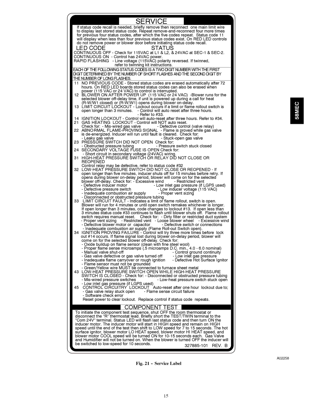
SERVICE
If status code recall is needed, briefly remove then reconnect one main limit wire to display last stored status code. Repeat
LED CODE | STATUS |
CONTINUOUS OFF - Check for 115VAC at L1 & L2, & 24VAC at
RAPID FLASHING - Line voltage (115VAC) polarity reversed. If twinned, refer to twinning kit instructions.
EACH OF THE FOLLOWING STATUS CODES IS A TWO DIGIT NUMBER WITH THE FIRST DIGIT DETERMINED BY THE NUMBER OF SHORT FLASHES AND THE SECOND DIGIT BY THE NUMBER OF LONG FLASHES.
11 | NO PREVIOUS CODE - Stored status codes are erased automatically after 72 | ||||
| hours. On RED LED boards stored status codes can also be erased when | ||||
12 | power (115 VAC or 24 VAC) to control is interrupted. |
| |||
BLOWER ON AFTER POWER UP (115 VAC or 24 VAC) | |||||
| selected blower | ||||
13 |
| ||||
LIMIT CIRCUIT LOCKOUT - Lockout occurs if a limit or flame rollout switch is | |||||
| open longer than 3 minutes. - Control will auto reset after three hours. | ||||
14 |
| - Refer to #33. |
|
| |
IGNITION LOCKOUT - Control will | |||||
21 | GAS HEATING LOCKOUT - Control will NOT auto reset. |
| |||
22 | Check for: - | - Defective control (valve relay) | |||
ABNORMAL | |||||
| is | ||||
23 | - Leaky gas valve |
| - | ||
PRESSURE SWITCH DID NOT OPEN Check for: |
| ||||
24 | - Obstructed pressure tubing |
| - Pressure switch stuck closed | ||
SECONDARY VOLTAGE FUSE IS OPEN Check for: |
| ||||
31 | - Short circuit in secondary voltage (24VAC) wiring. |
| |||
| REOPENED |
|
|
|
|
32 | Control relay may be defective, refer to status code #32 |
| |||
| open longer than five minutes, inducer shuts off for 15 minutes before retry. If | ||||
| opens during blower | ||||
| blower | - Restricted vent | |||
| - Defective inducer motor |
| - Low inlet gas pressure (if LGPS used) | ||
| - Defective pressure switch |
| - Low inducer voltage (115 VAC) | ||
| - Inadequate combustion air supply | - Proper vent sizing |
| ||
33 | - Disconnected or obstructed pressure tubing |
|
| ||
LIMIT CIRCUIT FAULT - Indicates a limit or flame rollout, switch is open. | |||||
| Blower will run for 4 minutes or until open switch remakes whichever is longer. | ||||
| If open longer than 3 minutes, code changes to lockout #13. If open less than | ||||
| 3 minutes status code #33 continues to flash until blower shuts off. Flame rollout | ||||
| switch requires manual reset. Check for: - Dirty filter or restricted duct system | ||||
| - Proper vent sizing - Restricted vent | - Loose blower wheel | - Excessive wind | ||
| - Defective blower motor or capacitor | - Defective switch or connections | |||
34 | - Inadequate combustion air supply (Flame | ||||
IGNITION PROVING FAILURE - Control will try three more times before lock | |||||
| out #14 occurs. If flame signal lost during blower | ||||
| come on for the selected blower |
| |||
| - Oxide buildup on flame sensor (clean with fine steel wool) |
| |||
| - Proper flame sense microamps (.5 microamps D.C. min., 4.0 - 6.0 nominal) | ||||
| - Manual valve |
|
| - Control ground continuity | |
| - Gas valve defective or gas valve turned off | - Low inlet gas pressure | |||
| - Inadequate flame carryover or rough ignition | - Defective Hot Surface Ignitor | |||
| - Flame sensor must not be grounded |
|
|
| |
43 | - Green/Yellow wire MUST be connected to furnace sheet metal | ||||
| |||||
| SWITCH IS CLOSED - Check for: - Disconnected or obstructed pressure tubing | ||||
| - |
| - | ||
45 | - Low inlet gas pressure (if LGPS used) |
|
| ||
CONTROL CIRCUITRY LOCKOUT | |||||
| - Gas valve relay stuck open | - Flame sense circuit failure |
| ||
| - Software check error |
|
|
| repeats. |
| Reset power to clear lockout. Replace control if status code | ||||
COMPONENT TEST
To initiate the component test sequence, shut OFF the room thermostat or disconnect the "R" thermostat lead. Briefly short the TEST/TWIN terminal to the "Com 24V" terminal. Status LED will flash last status code and then turn ON the
inducer motor. The inducer motor will start in HIGH speed and remain on HIGH speed until the end of the test then shift to LOW speed for 7 to 15 seconds. The hot
surface ignitor, blower motor LO HEAT speed, blower motor HI HEAT speed, and | |
blower motor COOL speed will be turned ON for | |
and Humidifier will not be turned on. When the blower is turned OFF the inducer will | |
be switched to | |
| |
Fig. 21 - Service Label
58MEC
A02258
15