58MEC
A99118
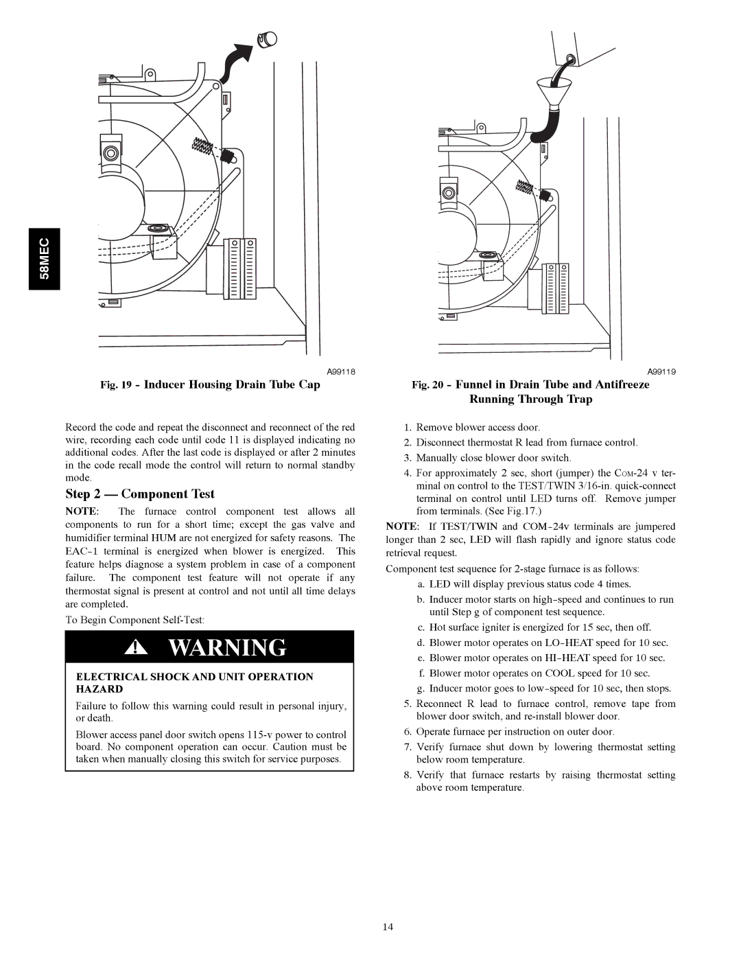
Fig. 19 - Inducer Housing Drain Tube Cap
Record the code and repeat the disconnect and reconnect of the red wire, recording each code until code 11 is displayed indicating no additional codes. After the last code is displayed or after 2 minutes in the code recall mode the control will return to normal standby mode.
Step 2 — Component Test
NOTE: The furnace control component test allows all components to run for a short time; except the gas valve and humidifier terminal HUM are not energized for safety reasons. The
To Begin Component
!WARNING
ELECTRICAL SHOCK AND UNIT OPERATION HAZARD
Failure to follow this warning could result in personal injury, or death.
Blower access panel door switch opens
A99119
Fig. 20 - Funnel in Drain Tube and Antifreeze
Running Through Trap
1.Remove blower access door.
2.Disconnect thermostat R lead from furnace control.
3.Manually close blower door switch.
4.For approximately 2 sec, short (jumper) the
NOTE: If TEST/TWIN and
Component test sequence for
a.LED will display previous status code 4 times.
b.Inducer motor starts on
c.Hot surface igniter is energized for 15 sec, then off.
d.Blower motor operates on
e.Blower motor operates on
f.Blower motor operates on COOL speed for 10 sec.
g.Inducer motor goes to
5.Reconnect R lead to furnace control, remove tape from blower door switch, and
6.Operate furnace per instruction on outer door.
7.Verify furnace shut down by lowering thermostat setting below room temperature.
8.Verify that furnace restarts by raising thermostat setting above room temperature.
14
