58MEC
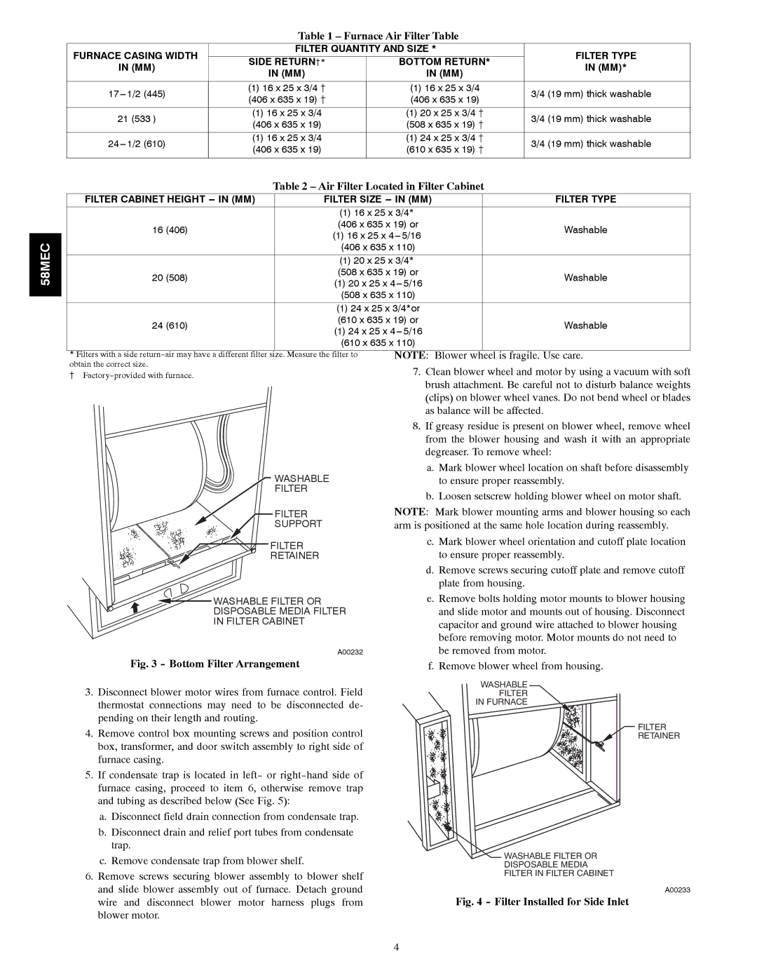
Table 1 – Furnace Air Filter Table
|
|
|
|
| |
FURNACE CASING WIDTH | FILTER QUANTITY AND SIZE * |
| FILTER TYPE | ||
IN (MM) | SIDE RETURN{* | BOTTOM RETURN* | IN (MM)* | ||
IN (MM) | IN (MM) |
| |||
|
|
| |||
|
|
|
| ||
(1) 16 x 25 x 3/4 { | (1) 16 x 25 x 3/4 | 3/4 (19 mm) thick washable | |||
(406 x 635 x 19) { | (406 x 635 x 19) | ||||
|
| ||||
|
|
|
| ||
21 (533 ) | (1) 16 x 25 x 3/4 | (1) 20 x 25 x 3/4 { | 3/4 (19 mm) thick washable | ||
(406 x 635 x 19) | (508 x 635 x 19) | { | |||
|
| ||||
|
|
|
| ||
(1) 16 x 25 x 3/4 | (1) 24 x 25 x 3/4 { | 3/4 (19 mm) thick washable | |||
(406 x 635 x 19) | (610 x 635 x 19) | { | |||
|
| ||||
|
|
|
|
| |
Table 2 – Air Filter Located in Filter Cabinet
FILTER CABINET HEIGHT | FILTER SIZE | FILTER TYPE | |
| (1) 16 x 25 x 3/4* |
| |
16 (406) | (406 x 635 x 19) or | Washable | |
(1) 16 x 25 x | |||
|
| ||
| (406 x 635 x 110) |
| |
|
|
| |
| (1) 20 x 25 x 3/4* |
| |
20 (508) | (508 x 635 x 19) or | Washable | |
(1) 20 x 25 x | |||
|
| ||
| (508 x 635 x 110) |
| |
|
|
| |
| (1) 24 x 25 x 3/4*or |
| |
24 (610) | (610 x 635 x 19) or | Washable | |
(1) 24 x 25 x | |||
|
| ||
| (610 x 635 x 110) |
|
|
|
|
* Filters with a side | NOTE: Blower wheel is fragile. Use care. | |
obtain the correct size. | 7. Clean blower wheel and motor by using a vacuum with soft | |
{ | ||
| brush attachment. Be careful not to disturb balance weights | |
| (clips) on blower wheel vanes. Do not bend wheel or blades | |
| as balance will be affected. | |
| 8. If greasy residue is present on blower wheel, remove wheel | |
| from the blower housing and wash it with an appropriate | |
| degreaser. To remove wheel: | |
WASHABLE | a. Mark blower wheel location on shaft before disassembly | |
to ensure proper reassembly. | ||
FILTER | b. Loosen setscrew holding blower wheel on motor shaft. | |
| ||
FILTER
SUPPORT
FILTER
RETAINER
WASHABLE FILTER OR
DISPOSABLE MEDIA FILTER
IN FILTER CABINET
A00232
Fig. 3 - Bottom Filter Arrangement
3.Disconnect blower motor wires from furnace control. Field thermostat connections may need to be disconnected de- pending on their length and routing.
4.Remove control box mounting screws and position control box, transformer, and door switch assembly to right side of furnace casing.
5.If condensate trap is located in left- or
a.Disconnect field drain connection from condensate trap.
b.Disconnect drain and relief port tubes from condensate trap.
c.Remove condensate trap from blower shelf.
6.Remove screws securing blower assembly to blower shelf and slide blower assembly out of furnace. Detach ground wire and disconnect blower motor harness plugs from blower motor.
NOTE: Mark blower mounting arms and blower housing so each arm is positioned at the same hole location during reassembly.
c.Mark blower wheel orientation and cutoff plate location to ensure proper reassembly.
d.Remove screws securing cutoff plate and remove cutoff plate from housing.
e.Remove bolts holding motor mounts to blower housing and slide motor and mounts out of housing. Disconnect capacitor and ground wire attached to blower housing before removing motor. Motor mounts do not need to be removed from motor.
f.Remove blower wheel from housing.
WASHABLE
FILTER
IN FURNACE
FILTER
RETAINER
WASHABLE FILTER OR
DISPOSABLE MEDIA
FILTER IN FILTER CABINET
A00233
Fig. 4 - Filter Installed for Side Inlet
4
