Manuals
/
Carrier
/
Household Appliance
/
Air Conditioner
Carrier
90MA
specifications
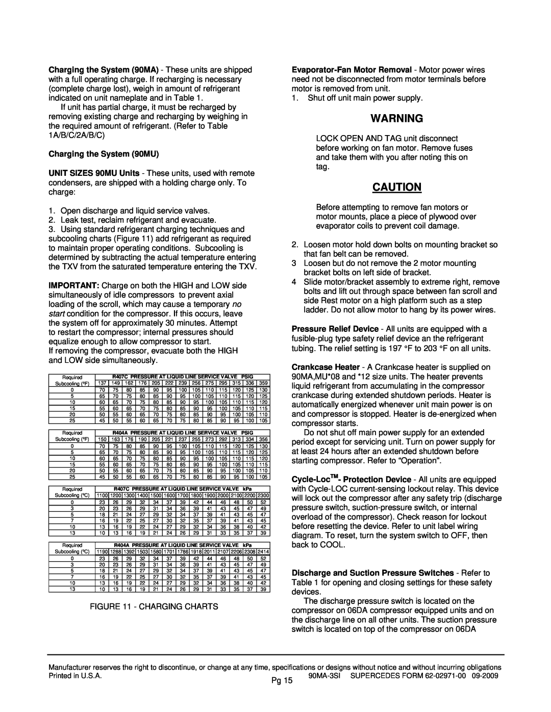
Charging the System 90MU
Models:
90MU
90MA
1
15
22
22
Download
22 pages
24.03 Kb
12
13
14
15
16
17
18
19
Dimension
Service
Page 15
Image 15
Page 14
Page 16
Page 15
Image 15
Page 14
Page 16
Contents
Installation, Operation and Service Instructions
Single-PackageMarine Cooling Units
COMPONENT ARRANGEMENT - *04/*06
COMPONENT ARRANGEMENT - *08/*12
ODF = Outside Diameter Female
FPT = Female Pipe Thread MPT = Male Pipe Thread
FPT = Female Pipe Thread MPT = Male Pipe Thread
Page
ODF = Outside Diameter Female
FPT = Female Pipe Thread MPT = Male Pipe Thread
ODF = Outside Diameter Female
FPT = Female Pipe Thread MPT = Male Pipe Thread
FPT = Female Pipe Thread MPT = Male Pipe Thread
TYPICAL UNIT SHOWN
FIGURE 2 - UNIT DIMENSIONS
Step 4 - Rig and Place Unit
FIGURE 1 - BASE UNIT INTERIOR DETAILS
FIGURE 5 - TYPICAL CONDENSER WATER PIPING
FIGURE 3 - HORIZONTAL WHEEL CENTERING
FIGURE 4 - CONCENTRIC WHEEL ALIGNMENT
Step 10 - Make Condenser Connections
FIGURE 6 - CONNECTION LOCATIONS
FIGURE 7 - CONDENSATE DRAIN TRAP
To Shut Down Unit
OPERATION
Step 12 - Make Electrical Connections
To start unit
SERVICE
FIGURE 8 - FAN PULLEY ADJUSTMENT
Return-AirGrille Removal
Water Regulating Valve
FIGURE 9 - GRAVITY FLOW METHOD
FIGURE 10 - FORCED CIRCULATION METHOD
Charging the System 90MU
R-407C, R-404A,and R-134aunits
FIGURE 12 WIRING SCHEMATIC - 90MA/MU*04/*06
FOR NOTES AND LEGEND, SEE FIGURE
90MA-3SISUPERCEDES FORM
90MA-3SISUPERCEDES FORM
FIGURE 13 COMPONENT ARRANGEMENT - 90MA/MU*04/*06
FIGURE 14 - ELECTRICAL SCHEMATIC - 90MA/MU*08/*12
FOR NOTES AND LEGEND, SEE FIGURE
90MA-3SISUPERCEDES FORM
90MA-3SISUPERCEDES FORM
90MA-3SISUPERCEDES FORM
90MA-3SISUPERCEDES FORM
Top
Page
Image
Contents