Manuals
/
Carrier
/
Household Appliance
/
Air Conditioner
Carrier
90MA Rig and Place Unit, Base Unit Interior Details, Typical Unit Shown, Unit Dimensions
Models:
90MU
90MA
1
8
22
22
Download
22 pages
24.03 Kb
5
6
7
8
9
10
11
12
Dimension
Service
Page 8
Image 8
Page 7
Page 9
Page 8
Image 8
Page 7
Page 9
Contents
Single-PackageMarine Cooling Units
COMPONENT ARRANGEMENT - *04/*06
COMPONENT ARRANGEMENT - *08/*12
Installation, Operation and Service Instructions
FPT = Female Pipe Thread MPT = Male Pipe Thread
ODF = Outside Diameter Female
FPT = Female Pipe Thread MPT = Male Pipe Thread
Page
FPT = Female Pipe Thread MPT = Male Pipe Thread
ODF = Outside Diameter Female
FPT = Female Pipe Thread MPT = Male Pipe Thread
ODF = Outside Diameter Female
FPT = Female Pipe Thread MPT = Male Pipe Thread
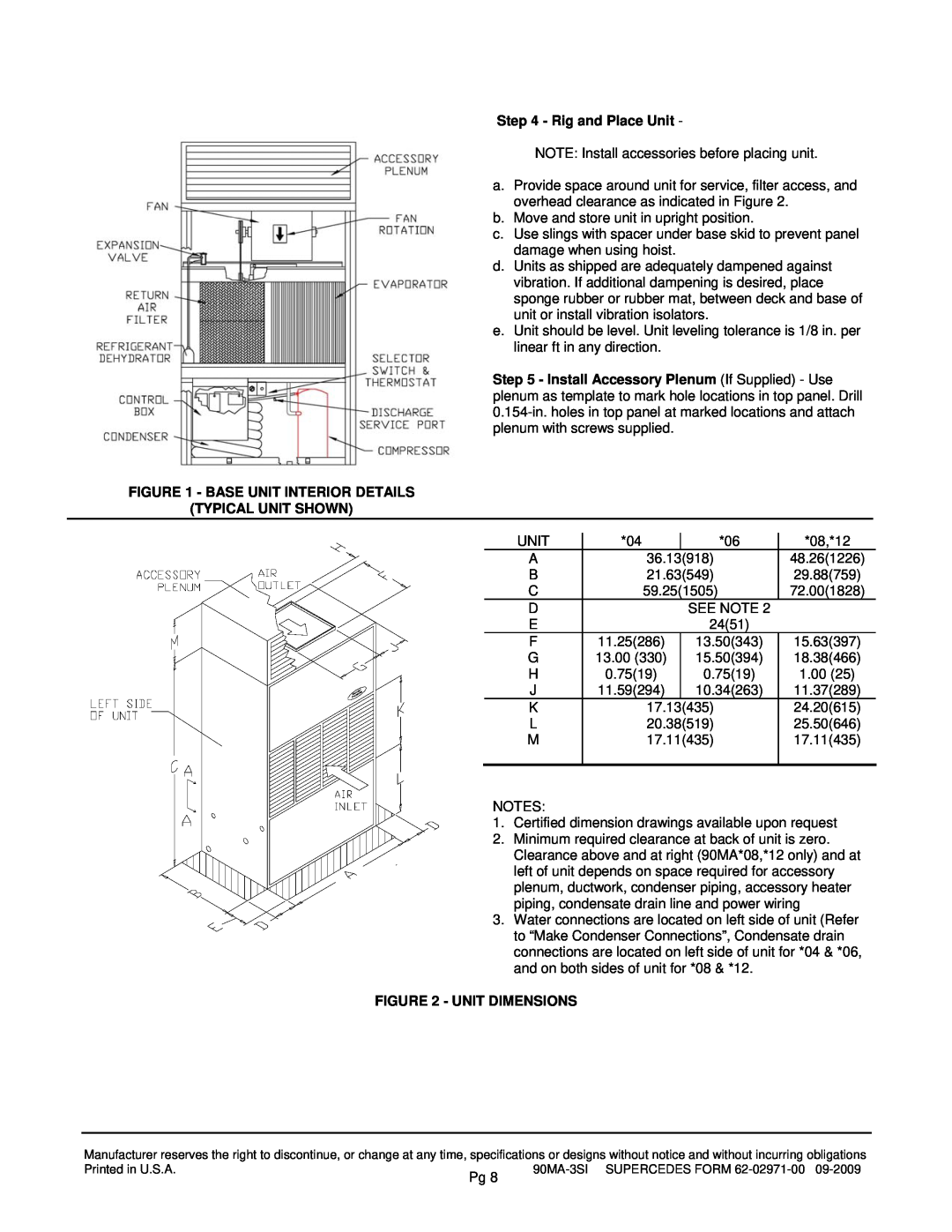
FIGURE 2 - UNIT DIMENSIONS
Step 4 - Rig and Place Unit
FIGURE 1 - BASE UNIT INTERIOR DETAILS
TYPICAL UNIT SHOWN
FIGURE 3 - HORIZONTAL WHEEL CENTERING
FIGURE 4 - CONCENTRIC WHEEL ALIGNMENT
Step 10 - Make Condenser Connections
FIGURE 5 - TYPICAL CONDENSER WATER PIPING
FIGURE 6 - CONNECTION LOCATIONS
FIGURE 7 - CONDENSATE DRAIN TRAP
OPERATION
Step 12 - Make Electrical Connections
To start unit
To Shut Down Unit
Return-AirGrille Removal
SERVICE
FIGURE 8 - FAN PULLEY ADJUSTMENT
FIGURE 10 - FORCED CIRCULATION METHOD
Water Regulating Valve
FIGURE 9 - GRAVITY FLOW METHOD
Charging the System 90MU
R-407C, R-404A,and R-134aunits
90MA-3SISUPERCEDES FORM
FIGURE 12 WIRING SCHEMATIC - 90MA/MU*04/*06
FOR NOTES AND LEGEND, SEE FIGURE
FIGURE 13 COMPONENT ARRANGEMENT - 90MA/MU*04/*06
90MA-3SISUPERCEDES FORM
90MA-3SISUPERCEDES FORM
FIGURE 14 - ELECTRICAL SCHEMATIC - 90MA/MU*08/*12
FOR NOTES AND LEGEND, SEE FIGURE
90MA-3SISUPERCEDES FORM
90MA-3SISUPERCEDES FORM
90MA-3SISUPERCEDES FORM
Top
Page
Image
Contents