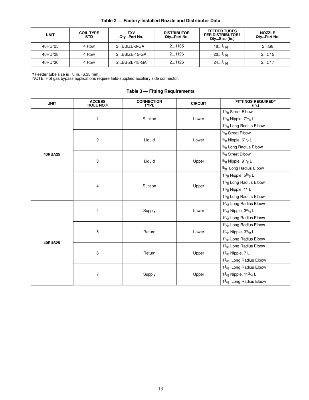
Table 2 — Factory-Installed Nozzle and Distributor Data
| COIL TYPE | TXV | DISTRIBUTOR | FEEDER TUBES | NOZZLE | |
UNIT | PER DISTRIBUTOR† | |||||
STD | Qty...Part No. | Qty...Part No. | Qty...Part No. | |||
| Qty...Size (in.) | |||||
|
|
|
|
| ||
|
|
|
|
|
| |
40RU*25 | 4 Row | 2...1135 | 18...3/16 | 2...G6 | ||
40RU*28 | 4 Row | 2...1126 | 20...3/16 | 2...C15 | ||
40RU*30 | 4 Row | 2...1126 | 24...3/16 | 2...C17 |
† Feeder tube size is 1/4 in. (6.35 mm).
NOTE: Hot gas bypass applications require
Table 3 — Fitting Requirements
UNIT | ACCESS | CONNECTION | CIRCUIT |
| FITTINGS REQUIRED† |
HOLE NO.‡ | TYPE |
| (in.) | ||
|
|
| |||
|
|
|
| 11/8 Street Elbow | |
| 1 | Suction | Lower | 11/8 Nipple, 75/8 L | |
|
|
|
| 11/8 Long Radius Elbow | |
|
|
|
| 5/8 Street Elbow | |
| 2 | Liquid | Lower | 5/8 Nipple, 61/2 L | |
|
|
|
| 5/8 Long Radius Elbow | |
40RUA25 |
|
|
| 5/8 Street Elbow | |
| 3 | Liquid | Upper | 5/8 Nipple, 91/2 L | |
|
|
|
| 5/8 | Long Radius Elbow |
|
|
|
| 11/8 Nipple, 55/8 L | |
| 4 | Suction | Upper | 11/8 Long Radius Elbow | |
| 11/8 Nipple, 11 L | ||||
|
|
|
| ||
|
|
|
| 11/8 Long Radius Elbow | |
|
|
|
| 13/8 Long Radius Elbow | |
| 4 | Supply | Lower | 13/8 Nipple, 33/4 L | |
|
|
|
| 13/8 Long Radius Elbow | |
|
|
|
| 13/8 Long Radius Elbow | |
| 5 | Return | Lower | 13/8 Nipple, 33/8 L | |
40RUS25 |
|
|
| 13/8 Long Radius Elbow | |
|
|
| 13/8 Long Radius Elbow | ||
|
|
|
| ||
| 6 | Return | Upper | 13/8 Nipple, 7 L | |
|
|
|
| 13/8 | Long Radius Elbow |
|
|
|
| 13/8 | Long Radius Elbow |
| 7 | Supply | Upper | 13/8 Nipple, 113/4 L | |
|
|
|
| 13/8 | Long Radius Elbow |
13