| TXV | EQUALIZER LINE | ||
UPPER |
|
|
| |
SENSING |
|
| ||
SPLIT | BULB |
|
|
|
|
|
|
| SOLENOID* |
|
|
|
| VALVE |
|
| TXV |
| SIGHT |
AIRFLOW | 15 DIAMS |
| GLASS | |
| MIN | 10 |
|
|
|
| DIAMS |
|
|
|
| 8 DIAMS |
|
|
|
| MIN |
|
|
|
| EQUALIZER | FILTER | |
| TXV | LINE | ||
LOWER | SENSING |
| DRIER | |
SPLIT | BULB |
|
|
|
AIRFLOW | 15 DIAMS | TXV |
|
|
10 |
|
| ||
| MIN |
|
| |
|
| DIAMS |
|
|
|
| 8 DIAMS |
|
|
|
| MIN | INDOOR | |
|
|
| COIL |
|
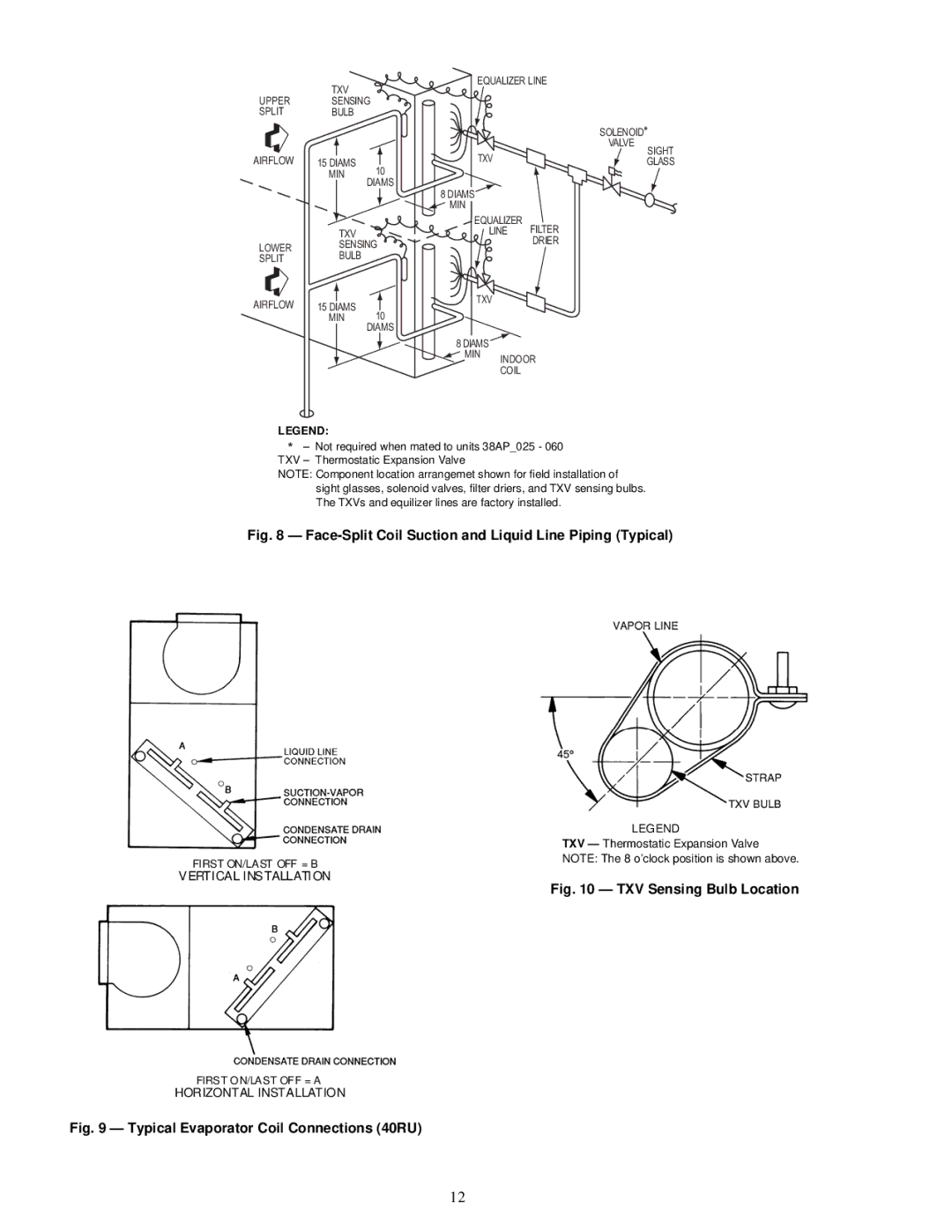
LEGEND:
*– Not required when mated to units 38AP_025 - 060 TXV – Thermostatic Expansion Valve
NOTE: Component location arrangemet shown for field installation of sight glasses, solenoid valves, filter driers, and TXV sensing bulbs. The TXVs and equilizer lines are factory installed.
Fig. 8 — Face-Split Coil Suction and Liquid Line Piping (Typical)
FIRST ON/LAST OFF = B
VERTICAL INSTALLATION
LEGEND
TXV — Thermostatic Expansion Valve NOTE: The 8 o’clock position is shown above.
Fig. 10 — TXV Sensing Bulb Location
FIRST ON/LAST OFF = A
HORIZONTAL INSTALLATION
Fig. 9 — Typical Evaporator Coil Connections (40RU)
12