Thermostat | Fan Coil | Heat Pump |
Thermostat
Fan Coil | Air Conditioner |
Heat
Cool
Fan
24VAC
*Common
O/B
W
Y
G
R
C
W
Y
G
R
C
O
W
Y
R
C
A08163
Heat |
|
|
W |
| |
Cool |
|
|
Y |
| |
Fan |
|
|
G |
| |
24VAC |
|
|
R |
| |
* Common |
|
|
C |
| |
|
|
|
W | W |
Y | Y |
G |
|
R | R |
C | C |
| A08164 |
TCSN
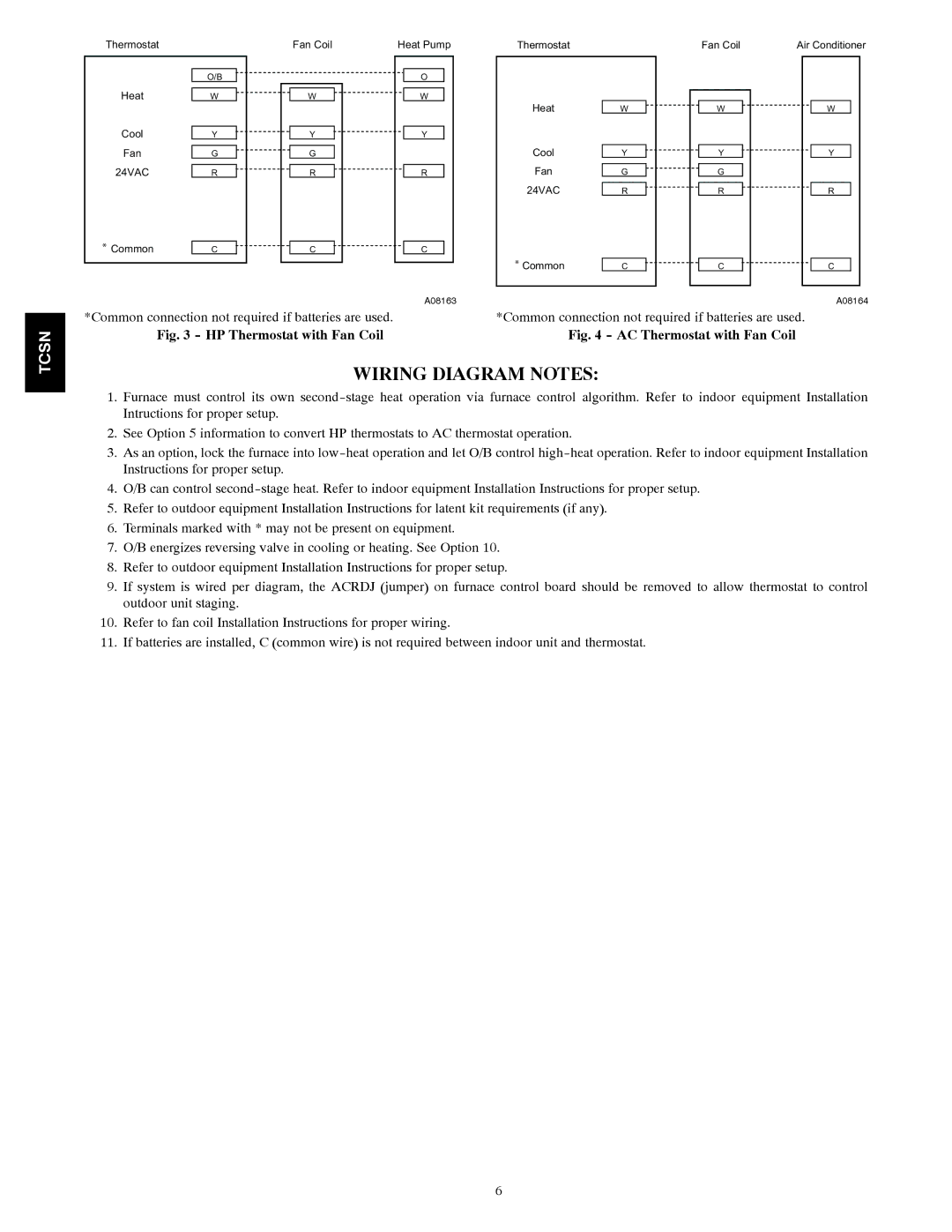
*Common connection not required if batteries are used.
Fig. 3 - HP Thermostat with Fan Coil
*Common connection not required if batteries are used.
Fig. 4 - AC Thermostat with Fan Coil
WIRING DIAGRAM NOTES:
1.Furnace must control its own
2.See Option 5 information to convert HP thermostats to AC thermostat operation.
3.As an option, lock the furnace into
4.O/B can control
5.Refer to outdoor equipment Installation Instructions for latent kit requirements (if any).
6.Terminals marked with * may not be present on equipment.
7.O/B energizes reversing valve in cooling or heating. See Option 10.
8.Refer to outdoor equipment Installation Instructions for proper setup.
9.If system is wired per diagram, the ACRDJ (jumper) on furnace control board should be removed to allow thermostat to control outdoor unit staging.
10.Refer to fan coil Installation Instructions for proper wiring.
11.If batteries are installed, C (common wire) is not required between indoor unit and thermostat.
6