Manuals
/
Carrier
/
Personal Care
/
Thermometer
Carrier
TP-NRH-A, TP-PRH-A
installation instructions
Press Tabs to Remove Backplate
Models:
TP-PRH-A
TP-NRH-A
1
13
88
88
Download
88 pages
49.23 Kb
10
11
12
13
14
15
16
17
Troubleshooting
Install
Wiring Diagrams
Energy Star Default Schedule
Option 02 Clean Filter Timer
Equipment On Indicators
Wiring
To Enter Configuration Mode
Mode Settings
Option 12 Smart Recovery
Page 13
Image 13
A07225
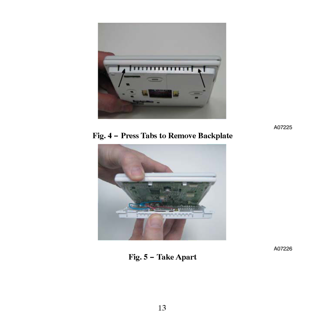
Fig. 4 − Press Tabs to Remove Backplate
A07226
Fig. 5 − Take Apart
13
Page 12
Page 14
Page 13
Image 13
Page 12
Page 14
Contents
Designed and Assembled
Programmable Control
USA
Safety Considerations
Table of Contents
Introduction
Power
Installation Considerations
Humidify Equipment and Connections
Models
Dehumidify Equipment and Connections
Outdoor Temperature Sensor TSTATCCSEN01−B
Two−Piece Thermidistat Control Configuration
Remote Indoor Temperature Sensor
Wiring
− TP−PRH−A Carton Contents
Installation
Thermidistat Control Location
− TP−NRH−A Carton Contents
Install Thermidistat Control
Unit Damage Hazard
Environmental Hazard
Two−Piece Installation
− Press Tabs to Remove Backplate
− Backplate Mounting
− Control Module Wiring Guide
− Secure Wires to Terminal Strip
− Attach Display to Backplate
− Equipment Control Module on Equipment
− Standoff
− Cover on Equipment Control Module
Single−Piece Installation
− Equipment Control Module
− Reattach Display Module
Set Thermidistat Control Configuration
Page
To Enter Configuration Mode
Option 02 Clean Filter Timer
Configuration Options -Selection
Option 01 Equipment Type
Option 04 Fan G On With W/W1
Option 03 Fahrenheit/Centigrade
Option 06 Cooling Lockout Below 55F/13C
Option 08 Auxiliary Heat Lockout Temperature
Option 07 Zoning
Option 10 Reversing Valve
Option 12 Smart Recovery
Option 11 Deadband Setting Between Heat & Cool
Option 13 Room Air Temperature Offset Adjust
Option 14 Humidity Display Offset Adjust
Option 17 Time Between Equipment Stages
Option 16 Maximum Cycles Per Hour
Option 19 Dry Contact Configuration programmable models only
Option 18 Backlight Configuration
Option 21 Keypad Lockout programmable models only
Option 20 Outdoor Air Temperature Offset Adjustment
Option 21 Keypad Lockout non−programmable models only
Page
Option 26 Minimum Cooling Setpoint
Option 28 UV Light Reminder
Option 27 Maximum Heating Setpoint
Option 29 Humidifier Pad Reminder
Option 30 Programmable Fan programmable models only
Option 33 Single or Two−Piece Installation
Option 40 Humidify Fan
Option 34 − Hybrid Heat Furnace Latch
Option 41 Variable Speed Blower
Option 43 Intelligent Heat Staging
Option 42 Variable Speed Super Dehumidification
Option 44 Super Comfort Heat
Option 99 Reset to Factory Defaults
System START−UP and Checkout
Energy Star Default Schedule
Final Settings
Page
Humidification
Humidity Control Features
Humidification Selections
To Select Humidification non−programmable
To Select Humidification programmable
Additional Humidify Comments
Dehumidification
− Auto Humidity
Additional Dehumidify Comments
Dehumidify Output and Equipment Connections
Vacation programmable models only
Vacation Setpoints
Vacation Setpoints Default Values
Vacation Humidification
Vacation Dehumidification
Cycle Timer
Timers
Ten−Minute Staging Timer
Operational Information
Three−Minute Minimum on Time
Defrost
Heat/Cool Setpoints Desired Temperature
Equipment On Indicators
Humidify and Dehumidify Indicators
Emergency Heat Mode
Dry Contact
Programmable Fan programmable models only
Relays
Temperature Offset After Power Cycle
Error Codes
Troubleshooting
Page
Equipment Configuration Outputs
− Equipment Configuration Outputs
− Display to Equipment Control Module Connection
Wiring Diagrams
− FV/FK Fan Coil with 2−Stage Heat Pump
− Typical Fan Coil with Heat Pump
HUM
− FV/FK Fan Coil w/2−Stage Air Conditioner
− Typical Fan Coil with Air Conditioner
A09169
− FV/FK Fan Coil with 1−Stage Heat Pump
− Typical Fan Coil Heating Only
HUM
− FV/FK Fan Coil with 1−Stage Air Conditioner
− Typical Fan Coil Cooling Only
A09121
− Single−Stage Furnace with Heat Pump Hybrid Heat
COM
− Single−Stage Furnace with Single−Speed Air Conditioner
A09125
− Single−Stage Furnace Heating Only
A09127
− Single−stage Furnace with Air Conditioner and Split Power
Mode Settings
Thermidistat Control Configuration Record
Configuration Options
Configuration Options
Option Fan Humidity Variable Speed Blower
Catalog No TP-PRH-4SI
Top
Page
Image
Contents