Page 9 of 15 |
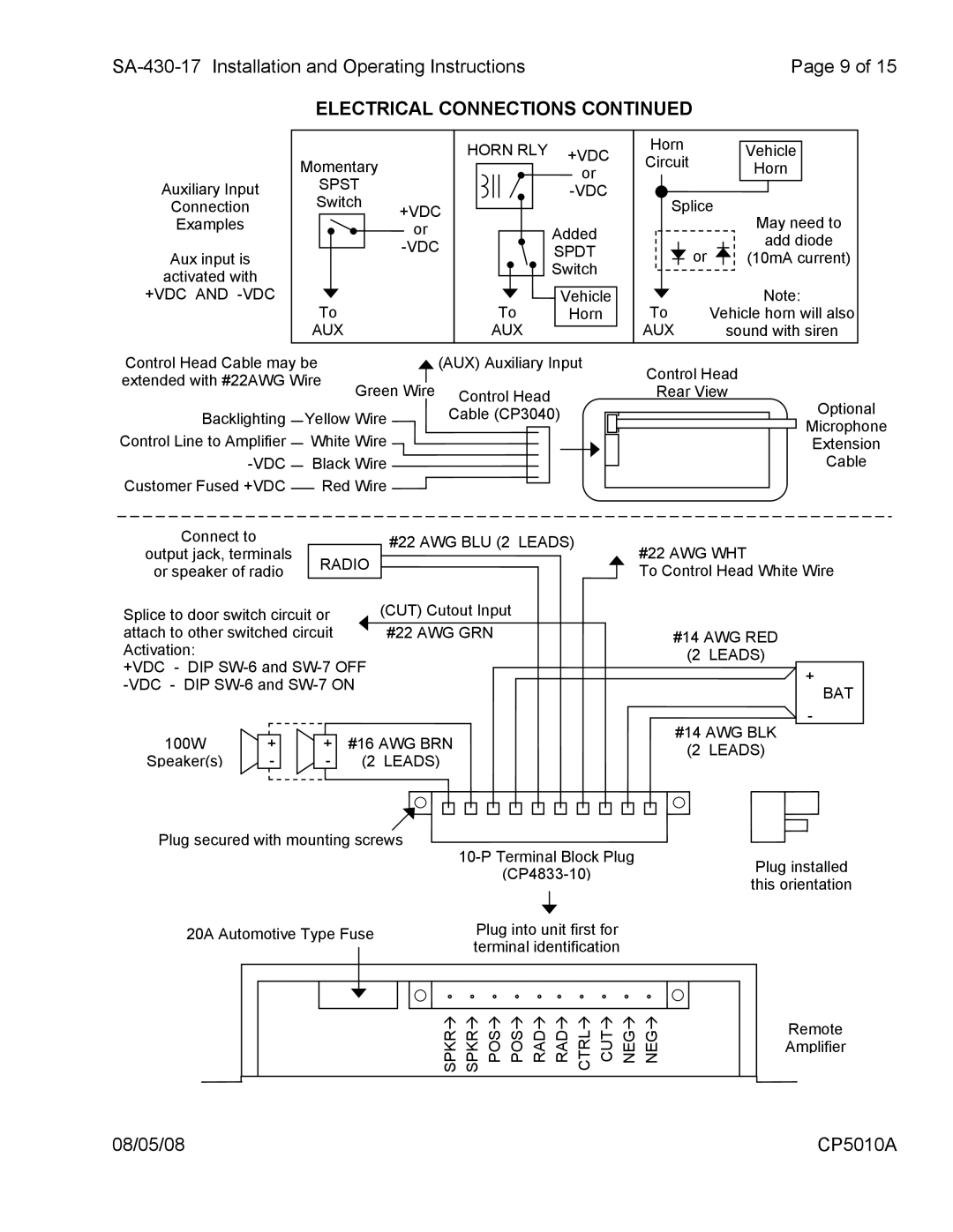
ELECTRICAL CONNECTIONS CONTINUED
Momentary
HORN RLY +VDC or
Horn
Circuit
Vehicle
Horn
Auxiliary Input
Connection
Examples
Aux input is
activated with
SPST
Switch
+VDC
or
![]() Added
Added
SPDT
Switch
Splice
or ![]()
May need to
add diode
(10mA current)
+VDC AND
To
AUX
Vehicle
To Horn
AUX
To | Note: |
Vehicle horn will also | |
AUX | sound with siren |
Control Head Cable may be |
| (AUX) Auxiliary Input | |||||
extended with #22AWG Wire | Green Wire | Control Head | |||||
|
|
|
| ||||
Backlighting |
| Yellow Wire | Cable (CP3040) | ||||
| |||||||
Control Line to Amplifier |
| White Wire |
|
|
| ||
|
|
|
| ||||
| Black Wire |
|
|
| |||
|
|
|
| ||||
Customer Fused +VDC |
|
|
| Red Wire |
|
|
|
|
|
|
|
|
| ||
|
|
|
|
|
| ||
Connect to |
| #22 AWG BLU (2 LEADS) | |
output jack, terminals | RADIO | ||
| |||
or speaker of radio |
| ||
|
|
Control Head
Rear View
Optional
Microphone
Extension
Cable
#22 AWG WHT
To Control Head White Wire
Splice to door switch circuit or | (CUT) Cutout Input |
attach to other switched circuit | #22 AWG GRN |
Activation: |
|
+VDC - DIP
100W | + |
| + | #16 AWG BRN | ||
Speaker(s) | - |
| - | (2 LEADS) | ||
|
|
|
|
|
|
|
Plug secured with mounting screws ![]()
#14 AWG RED
(2 LEADS)
+
BAT
-
#14 AWG BLK
(2 LEADS)
Plug installed this orientation
20A Automotive Type Fuse | Plug into unit first for |
| terminal identification |
NEGÆ
NEGÆ
CUTÆ
CTRLÆ
RADÆ
RADÆ
POSÆ
POSÆ
SPKRÆ
SPKRÆ
Remote Amplifier
08/05/08 | CP5010A |