M A G M A
the card into any available PCI slot and securing it with a retaining screw.
Step Two: Attach PCI Expansion and Power Cable(s)
Aset of four
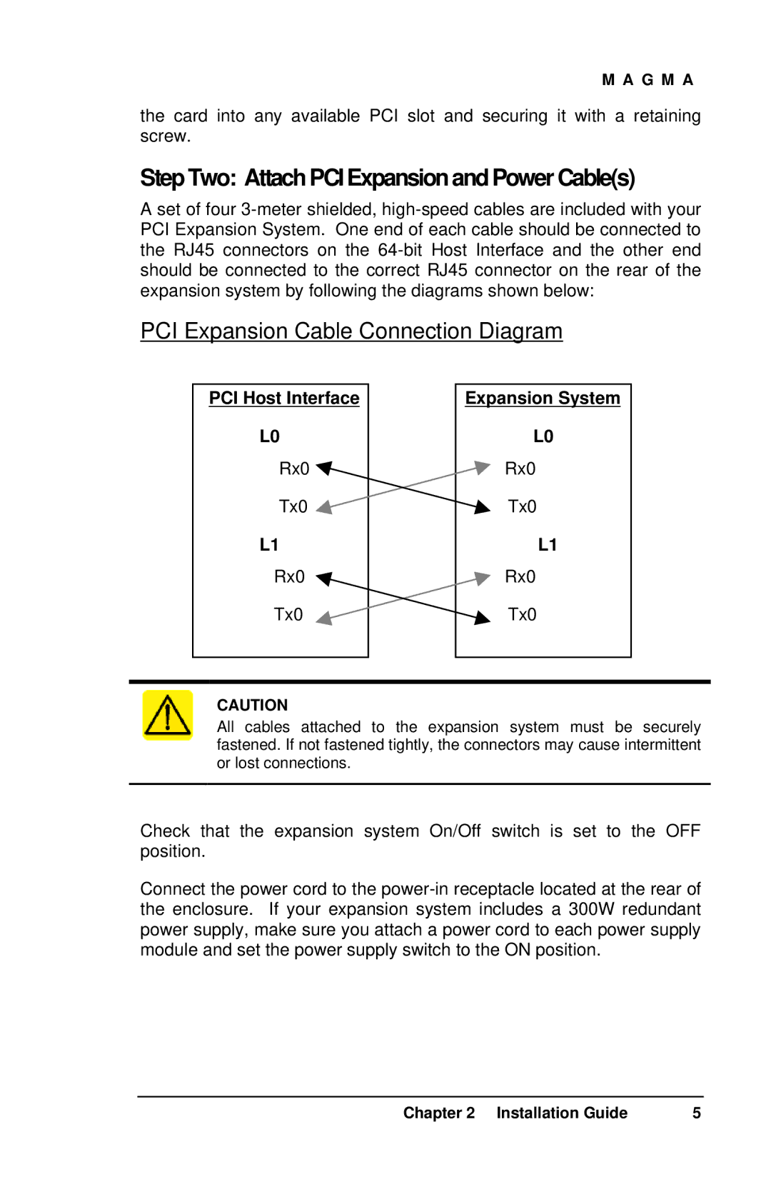
PCI Expansion Cable Connection Diagram
PCI Host Interface
L0
Rx0 ![]()
Tx0 ![]()
L1
Rx0
Tx0
Expansion System
L0
Rx0
Tx0
L1
Rx0
Tx0
CAUTION
All cables attached to the expansion system must be securely fastened. If not fastened tightly, the connectors may cause intermittent or lost connections.
Check that the expansion system On/Off switch is set to the OFF position.
Connect the power cord to the
Chapter 2 Installation Guide | 5 |