CONTROLS AND DISPLAYS
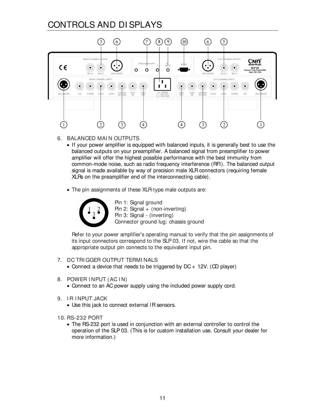
6.BALANCED MAIN OUTPUTS
•If your power amplifier is equipped with balanced inputs, it is generally best to use the balanced outputs on your preamplifier. A balanced signal from preamplifier to power amplifier will offer the highest possible performance with the best immunity from
•The pin assignments of these
Pin 1: Signal ground
Pin 2: Signal +
Pin 3: Signal - (inverting)
Connector ground lug: chassis ground
Refer to your power amplifier's operating manual to verify that the pin assignments of its input connectors correspond to the SLP 03. If not, wire the cable so that the appropriate output pin connects to the equivalent input pin.
7.DC TRIGGER OUTPUT TERMINALS
•Connect a device that needs to be triggered by DC + 12V. (CD player)
8.POWER INPUT (AC IN)
•Connect to an AC power supply using the included power supply cord.
9.IR INPUT JACK
•Use this jack to connect external IR sensors.
10.RS-232 PORT
•The
11