Cary Audio Design SLP 03 Rear Panel, Balanced Inputs, Pin 3 Signal - inverting, Cinema Bypass

Models: SLP 03

1 16
Download 16 pages 35.2 Kb
Page 11
Image 11
REAR PANEL

CONTROLS AND DISPLAYS
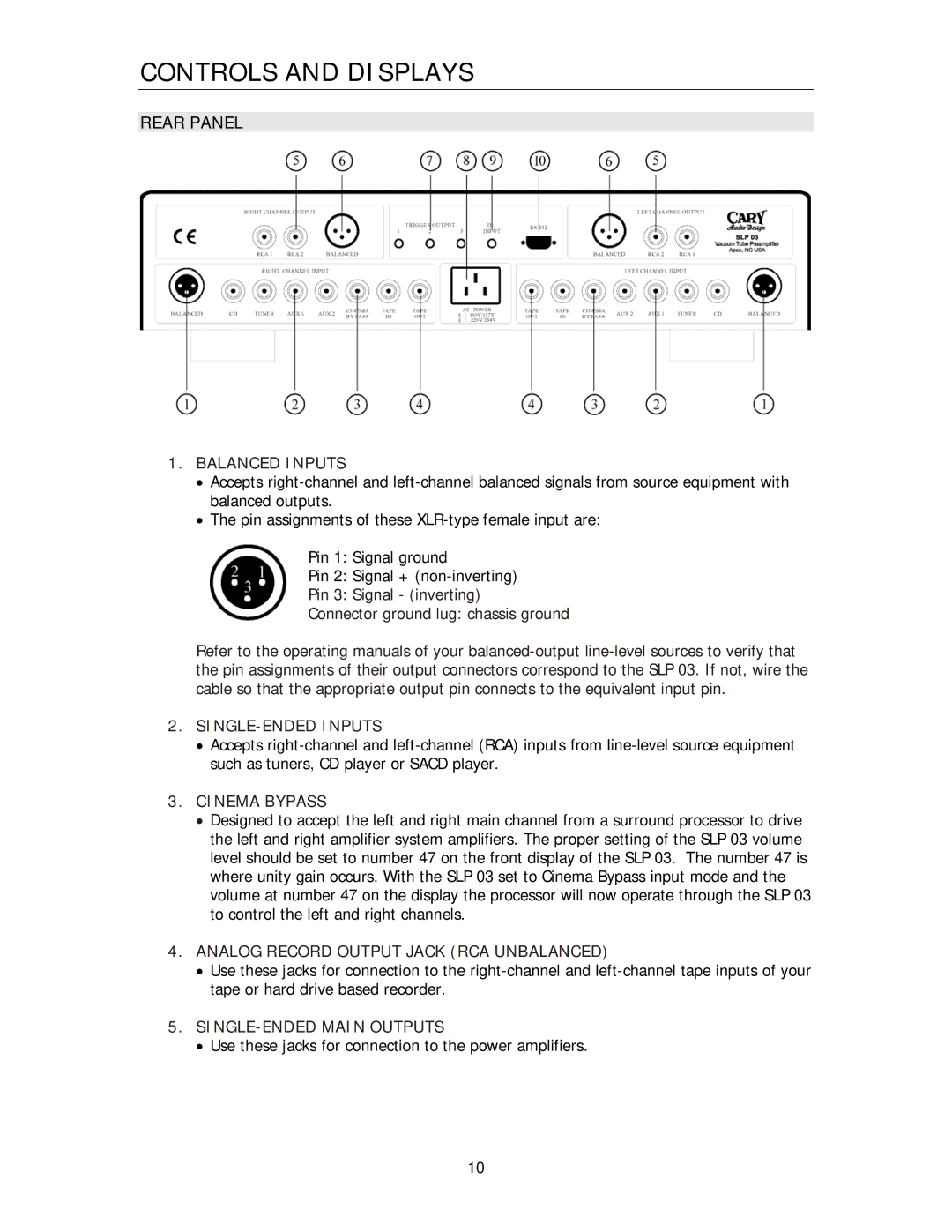
REAR PANEL

1.BALANCED INPUTS

Accepts right-channel and left-channel balanced signals from source equipment with balanced outputs.

The pin assignments of these XLR-type female input are:

Pin 1: Signal ground

Pin 2: Signal + (non-inverting)

Pin 3: Signal - (inverting)

Connector ground lug: chassis ground

Refer to the operating manuals of your balanced-output line-level sources to verify that the pin assignments of their output connectors correspond to the SLP 03. If not, wire the cable so that the appropriate output pin connects to the equivalent input pin.

2.SINGLE-ENDED INPUTS

Accepts right-channel and left-channel (RCA) inputs from line-level source equipment such as tuners, CD player or SACD player.

3.CINEMA BYPASS

Designed to accept the left and right main channel from a surround processor to drive the left and right amplifier system amplifiers. The proper setting of the SLP 03 volume level should be set to number 47 on the front display of the SLP 03. The number 47 is where unity gain occurs. With the SLP 03 set to Cinema Bypass input mode and the volume at number 47 on the display the processor will now operate through the SLP 03 to control the left and right channels.

4.ANALOG RECORD OUTPUT JACK (RCA UNBALANCED)

Use these jacks for connection to the right-channel and left-channel tape inputs of your tape or hard drive based recorder.

5.SINGLE-ENDED MAIN OUTPUTS

Use these jacks for connection to the power amplifiers.

10

Page 11
Image 11
Cary Audio Design SLP 03 Rear Panel, Balanced Inputs, Pin 3 Signal - inverting, Connector ground lug chassis ground