QV-R40
Introduction
Unpacking
Contents
Basic Image Recording
Deleting Files
Other Settings
Using the Camera with a Computer
SD logo is a registered trademark
Copyright Restrictions
Features
Introduction
General Precautions
Precautions
Smoke, abnormal odor, overheating, and other abnormalities
Connections
Transport
Water and Foreign Matter
Keep Away From Fire
Disassembly and Modification
Dropping and Rough Treatment
Locations To Be Avoided
Rechargeable Batteries
Batteries
Alkaline Batteries
Introduction
Charger Unit
AC Adaptor Option
Battery Life
Data Error Precautions
Operating conditions
Condensation
Lens
Other
Load the batteries
Quick Start Guide
First, charge the batteries
Inlet Type
To configure display language and clock settings
4, 5, 6, 7, 8
To record an image
To view a recorded image
To delete an image
Press SET to delete the image
Getting Ready
About This Manual
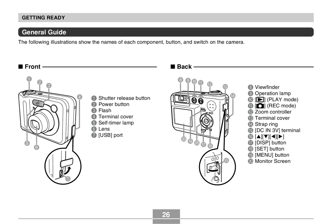
General Guide
Front Back
Bottom
REC mode
Monitor Screen Contents
Digital zoom indicator
Play mode
Changing the Contents of the Monitor Screen
Power Requirements
Attaching the Strap
To charge the batteries
Charging Batteries
Household Current
Plug the charger unit into a household power outlet
Getting Ready
Precautions During Use
Charger Unit Precautions
Battery Precautions
Storage Precautions
To load batteries
Optional Batteries
Low Battery Indicator
To remove the batteries from the camera
Battery Life Guidelines
Alkaline Battery Life
Tips to Make the Batteries Last Longer
Connect the AC power cord to the AC adaptor
Using AC Power
Battery Handling Precautions
AC Adaptor Precautions
To turn off the camera
Turning the Camera On and Off
To turn on the camera
Configuring Power Saving Settings
See page 45 for information about how to use menus
Using the On-screen Menus
Press the power button or the REC button
Use and to change the currently selected setting
Menu Screen Operations
Configuring Display Language and Clock Settings
To configure display language and clock settings
Set the current date and the time
Example October 23
Getting Ready
Basic Image Recording
Recording an Image
Press the shutter release button half way to focus the image
Operation Lamp and Focus Frame Operation
Recording Precautions
About the REC Mode Monitor Screen
About Auto Focus
Optical Zoom
Using the Optical Viewfinder
Using Zoom
REC mode, slide
Digital Zoom
Compose the image, and then press the shutter release button
Digital zoom indicator Zoom indicator
Record the image
Using the Flash
REC mode, press Menu Press to select Flash mode
Red operation lamp
Flash Unit Status
About Red-eye Reduction
Changing the Flash Intensity Setting
Flash Precautions
Using the Self-timer
Record the image
To specify the image size
Specifying Image Size and Quality
To specify image quality
Other Recording Functions
Using Auto Focus
Selecting the Focus Mode
REC mode, press
Specifying the Auto Focus Area
Other Recording Functions
Using the Macro Mode
Using the Infinity Mode
Press the shutter release button to record the image
Using Manual Focus
Keep pressing until the focus mode indicator shows MF
Using Focus Lock
Exposure Compensation EV Shift
Adjusting White Balance
Adjusting White Balance Manually
Press SET
Using the Best Shot Mode
Example Sample Scene
This enters the Best Shot mode and displays a sample scene
Creating Your Own Best Shot Setup
To delete a Best Shot user setup
Record the image
Focus frame
Other Recording Functions
REC mode, press Menu
Select the REC tab, select REC Mode,
Point the camera at
Using the Movie Mode
Select Movie, Then press SET
Subject and then Press the shutter Release button
Using the Histogram
Other Recording Functions
REC Mode Camera Settings
Specifying ISO Sensitivity
Selecting the Metering Mode
Using the Filter Function
Specifying Color Saturation
Specifying Contrast
Specifying Outline Sharpness
Turning the On-screen Grid On and Off
Turning Image Review On and Off
Assigning Functions to the and Keys
Specifying Power On Default Settings
Resetting the Camera
Press Play to Turn on the camera
Playback
Basic Playback Operation
Zooming the Display Image
To display
Resizing an Image
Cropping an Image
Play mode
Playing a Movie
Displaying the 9-image View
Display the 9-image view Use , , ,
Selecting a Specific Image in the 9- image View
Displaying the Calendar Screen
Play mode, slide the zoom controller twice towards
Rotating the Display Image
Using Image Roulette
100
101
Deleting a Single File
Deleting Files
102
Press SET to delete the file
Press SET to delete all the files
103
Deleting All Files
104
File Management
Memory Folders and Files
Folders
Protecting Files
To protect a single file
105
106
Dpof Settings File Name, number of copies
To protect all files in memory
To configure print settings for a single image
107
To configure print settings for all images
108
Exif Print
109
Print Image Matching
Using USB DIRECT-PRINT
110
111
112
Using the Favorite Folder
To copy a file to the Favorite folder
Disp
113
Use forward
To display a file in the Favorite folder
114
To delete a file from the Favorite folder
115
To delete all files from the Favorite folder
116
Specifying the File Name Serial Number Generation Method
Other Settings
117
Specifying an Image for the Startup Screen
118
Turning the Key Tone On and Off
119
Configuring Power Down Image Settings
To configure power down image settings
120
Change the name of the file to one of the following
Using the Alarm
To set an alarm
To disable the Power Down Image feature
121
Press Disp
Stopping the Alarm
122
123
Setting the Clock
To select your Home Time zone
124
To set the current time and date
Changing the Date Format
To display the World Time screen
To configure World Time settings
Using World Time
125
Use and to select World, and then Press
To configure summer time DST settings
126
127
After the setting is the way you want, press SET
Press SET again to exit the setting screen
Changing the Display Language
128
Formatting Built-in Memory
Using a Memory Card
129
To remove a memory card from the camera
Using a Memory Card
To insert a memory card into the camera
130
Formatting a Memory Card
131
Memory Card Precautions
132
Copying Files
To copy all the files in built-in memory to a memory card
133
Press Menu to exit the copy operation
To copy a file from a memory card to built-in memory
134
135
Using the Camera with a Windows Computer
Viewing Images on a Computer
Windows XP Users
136
Windows 98/Me/2000 Users
Click USB driver and then Install
137
138
Windows2000 Users
139
WindowsMe/98/XP Users
140
USB Connection Precautions
Using the Camera with a Macintosh Computer
141
142
143
Using a Computer with a Built-in PC Card Slot
Using a Memory Card to Transfer Images to a Computer
Using a Computer with a Built-in SD Memory Card Slot
144
145
Using a Commercially Available SD Memory Card Reader/Writer
DCF Protocol
Memory Data
146
Folder and File Contents
Memory Directory Structure
Directory Structure
147
Built-in Memory and Memory Card Precautions
Image Files Supported by the Camera
Creating an album
Using the Camera with a Computer
Using the Album Feature
148
Selecting an Album Layout
149
Background Color
Configuring Detailed Album Settings
150
Album Type
Auto Album Creation On/Off
151
Image Use
Web browser to open File named
Viewing Album Files
152
153
154
About the bundled CD-ROM
Installing the Software from the CD-ROM
Saving an Album
155
Windows
Computer System Requirements
156
Macintosh
Selecting a Language
Installing Software from the CD-ROM in Windows
Getting Started
157
158
Viewing the Contents of the Read me File
Installing an Application
159
User Registration
Exiting the Menu Application
To install Photo Loader
Installing Software
Installing Software from the CD-ROM on a Macintosh
160
To read the Photo Loader user’s guide
161
To view the camera user’s guide
To register as a user
162
REC mode
Appendix
Menu Reference
163
Play mode
Set Up tab menu
Play tab menu
Indicator Lamp Reference
164
165
Charger Unit
166
Troubleshooting Guide
167
168
169
Display Messages
170
171
Main Specifications
Specifications
Camera Functions
172
Approximate Memory Capacity and File sizes
Power Requirements
173
Special battery charger unit BC-5H Plug-in Type
Rechargeable nickel-metal hydride Battery HR-3UA
Special battery charger unit BC-5H Inlet Type
174
175