AUTOMATIC TRANSFER SWITCH
CT
CTS SERIES ACCESSORY DEFINITIONS
6P
Microprocessor activated test switch (Momentary)
6A
Hardwired test switch (Maintained)
6AP
Microprocessor activated test switch (Maintained)
6BK
Hardwired test switch (Maintained Auto – Momentary Test) Key operated
6CK
Hardwired test switch (Maintained Auto – Maintained Test) Key operated
A1
Auxiliary Contact S.P.D.T. – Normal (Source 1) Failure
A1E
Auxiliary Contact S.P.D.T. – Emergency (Source 2) Failure
A3
Auxiliary Contact – closed in emergency (Source 2) Additional available (10 max.) on CTS Series and need to be specified
A4
Auxiliary Contact – closed in normal (Source 1) Additional available (10 max.) on CTS Series and need to be specified
A62
Motor disconnect and staged restart (1 contact)
AB3
Auxiliary contact – closed in bypass emergency (Source 2) (S.P.D.T.) (Standard up to 400A) Additional available (10 max.) on CBTS Series and need to be specified
AB4
Auxiliary contact – closed in bypass emergency (Source 1) (S.P.D.T.) (Standard up to 400A) Additional available (10 max.) on CBTS Series and need to be specified
CALIBRATE
Microprocessor activated calibration feature
CDP
Programmable exerciser daily, 7/14/28/365 days
CDT
Exerciser no load timer
CTAP
Chicago transfer alarm panel mounted in door of enclosure. Includes 3 aux. contacts and fuse.
DS
Disconnect Switch. Disconnects source voltage to transfer power panel.
DT (DELAYED TRANSITION ONLY)
Time Delay from Neutral Switch position to Source 2 on retransfer
DW (DELAYED TRANSITION ONLY)
Time Delay from Neutral Switch position to Source 2 on retransfer
E
Engine Start Relay
EL/P
Event log of last 16 events
ETHERNET
Ethernet Communication Adapter. Requires Modbus Communication Module.
F
Fan contact, closed when engine runs.
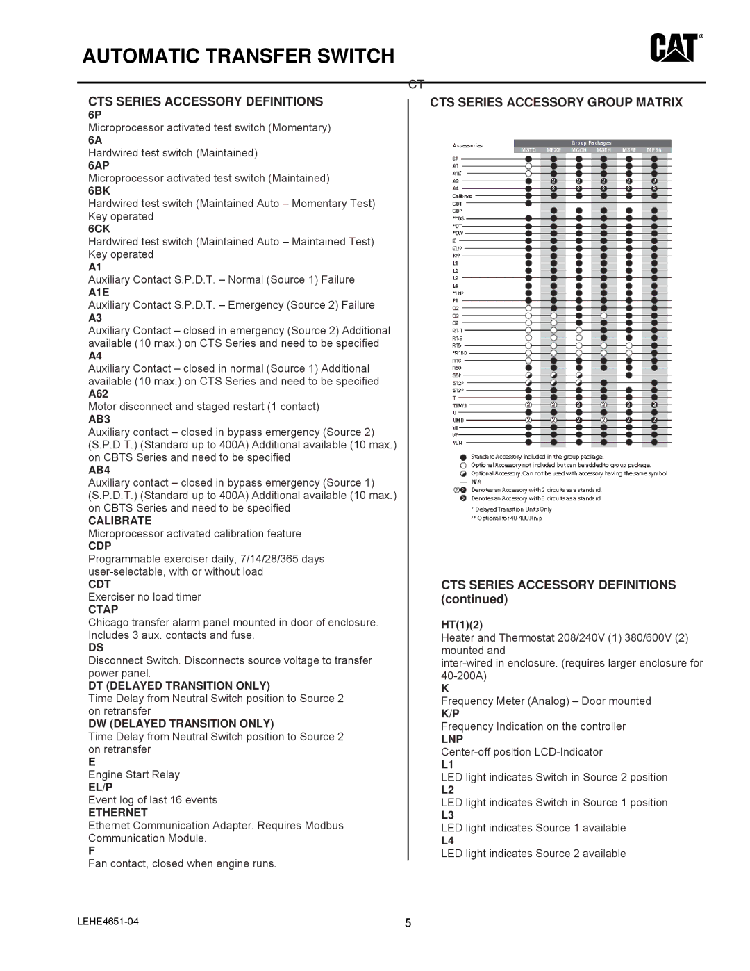
CTS SERIES ACCESSORY GROUP MATRIX
CTS SERIES ACCESSORY DEFINITIONS (continued)
HT(1)(2)
Heater and Thermostat 208/240V (1) 380/600V (2) mounted and
K
Frequency Meter (Analog) – Door mounted
K/P
Frequency Indication on the controller
LNP
L1
LED light indicates Switch in Source 2 position
L2
LED light indicates Switch in Source 1 position
L3
LED light indicates Source 1 available
L4
LED light indicates Source 2 available
5 |