ASSEMBLY INSTRUCTIONS
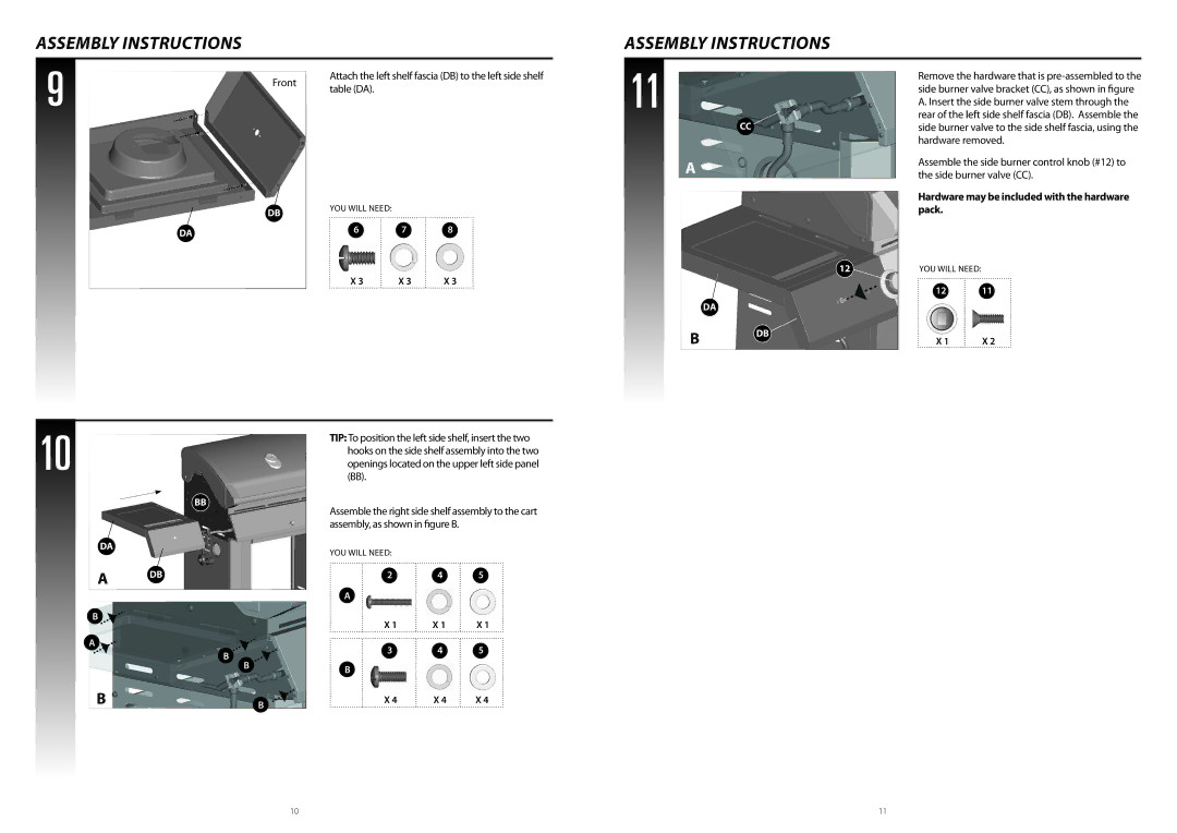
9 | Front | Attach the left shelf fascia (DB) to the left side shelf |
| ||
| table (DA). | |
|
|
| DB | YOU WILL NEED: |
|
|
|
|
|
| |
DA |
| 6 | 7 | 8 |
|
|
|
|
X 3 | X 3 | X 3 |
10 |
|
|
|
| (BB). |
|
|
|
|
|
|
| TIP: To position the left side shelf, insert the two | ||
|
|
|
|
| hooks on the side shelf assembly into the two | ||
|
|
|
|
| openings located on the upper left side panel | ||
|
| BB |
|
| Assemble the right side shelf assembly to the cart | ||
|
|
|
|
| |||
|
|
|
|
| assembly, as shown in figure B. |
| |
DA |
|
|
|
| YOU WILL NEED: |
|
|
|
|
|
|
|
|
| |
A | DB |
|
|
| 2 | 4 | 5 |
|
|
|
|
|
|
| |
|
|
|
|
| A |
|
|
B |
|
|
|
| X 1 | X 1 | X 1 |
|
|
|
|
| |||
A* |
| B |
|
| 3 | 4 | 5 |
|
| B |
|
|
|
| |
|
|
|
| B |
|
| |
|
|
|
|
|
|
| |
B |
|
|
| B | X 4 | X 4 | X 4 |
|
|
|
|
|
|
| |
ASSEMBLY INSTRUCTIONS
11 | Remove the hardware that is | |
| ||
| side burner valve bracket (CC), as shown in figure | |
| A. Insert the side burner valve stem through the | |
CC | rear of the left side shelf fascia (DB). Assemble the | |
side burner valve to the side shelf fascia, using the | ||
| hardware removed. | |
A | Assemble the side burner control knob (#12) to | |
the side burner valve (CC). | ||
| ||
| Hardware may be included with the hardware | |
| pack. |
| 12 | YOU WILL NEED: |
|
|
| 12 | 11 |
| DA |
|
|
B | DB | X 1 | X 2 |
|
10 | 11 |
