Fig. A
Fig. B
Fig. C
Orifice
removal out
Valve orifice is taken out
Fig. D
Inner orifice
for NG ![]()
4
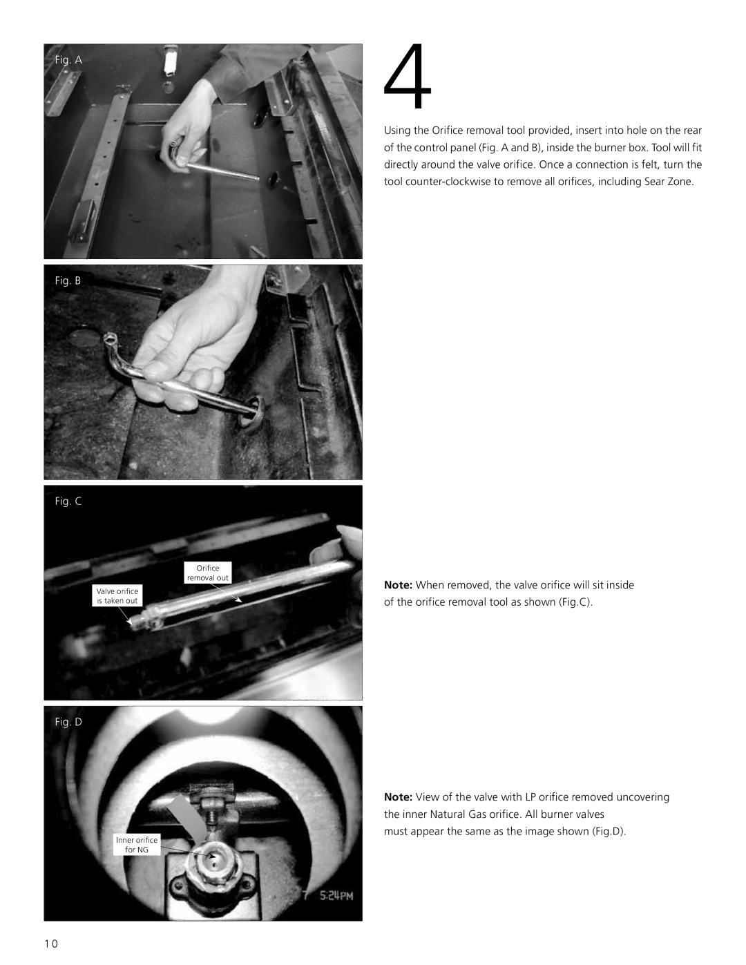
Using the Orifice removal tool provided, insert into hole on the rear of the control panel (Fig. A and B), inside the burner box. Tool will fit directly around the valve orifice. Once a connection is felt, turn the tool
Note: When removed, the valve orifice will sit inside of the orifice removal tool as shown (Fig.C).
Note: View of the valve with LP orifice removed uncovering the inner Natural Gas orifice. All burner valves
must appear the same as the image shown (Fig.D).
1 0
